background image

4590 Micro Reactors

P a r r   I n s t r u m e n t   C o m p a n y

14

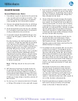
HOW TO  USE THE VESSEL

Removable Vessels

Always remove removable vessels from the support 
stand before attempting to open or close them.

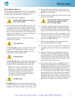
To open the Vessel 

Open the gas release valve to discharge any internal 
pressure.  For the bolted closure, loosen the six cap 
screws in the split ring sections.  Loosen the cone 
pointed screw in the outer band and lower the band 
to rest on the table.  The ring sections can now be 
removed, and the head with all attached fittings is free 
to be lifted from the cylinder.  Handle the head care-
fully so as not to damage the stirring shaft and other 
internals when they are outside of the cylinder.

Before Closing the Vessel

Examine the head gasket or o-ring carefully to be 
sure that it is in good condition.  After considerable 
use, some of the PTFE gasket may extrude into a 
thin, ragged edge around the inside and outside 
diameters.  This does not necessarily mean that the 
gasket must be replaced, but the extruded portion 
should be removed with a sharp knife.  Examine the 
mating surfaces on the cylinder and head to be sure 
they are clean and free from burrs; then set the head 
on the cylinder.

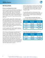
Sealing Vessels with PTFE Gaskets

Tighten each of the cap screws with the wrench 
furnished with the apparatus.  Apply a firm but hard 
pull to each screw.  If a torque wrench is available, 
apply 15 ft-lbs to each screw. 

 DO NOT apply more 

than 25 ft-lbs of torque to these bolts as this can 
deform the head of the reactor.

  Tightening should 

proceed in a criss-cross pattern rather than progres-
sively around the circle.  Let the vessel stand for 
about five minutes after the initial tightening; then 
tighten the cap screws again.  This will compensate 
for any tendency of the PTFE gasket to flow under 
the loading pressure.

Routinely inspect cap screws on the split ring closure 
for lubrication and cleanliness. It is important to clean 
and lubricate them periodically so that the required 
torque is achieved when tightening the bolts.

Sealing with Flexible Graphite Gaskets

Tighten the cap screws with enclosed wrench in 
same criss-cross pattern as the PTFE gasket.  Initially 
tighten the screws to 15 ft-lbs then increase to 20-25 
ft-lbs for proper seal.

Flexible graphite gaskets tend to be somewhat 
flakey. To extend the useful life of these gaskets, first 
rough up the sealing surface of the cylinder with 
120 grit sand paper to ensure the gasket remains in 
the head groove and does not stick to the cylinder. 
Secondly, coat both sealing surfaces with a silicone 
lubricant. This process will aid in compressing the 
gasket so it does not break apart after one use.

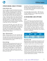
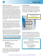
Recommended  Bolt Torque

PTFE

0-3000 psig  
(0-200 bar)

15-20 ft-lbs

PTFE or 
Flexible Graphite

3000-5000 psig 
(200-345 bar)

20-25 ft-lbs

O-Ring Closures

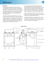
The split rings used with an o-ring seal do not 
include any compression bolts.

With the easy close split ring, the o-ring is attached 
to the pilot on the underside of the head.  When 
closing the vessel, set the head on the cylinder and 
press down on the head until the bottom of the head 
meets with the cylinder flange.  Then install the two 
split ring halves and attach the outer drop band.

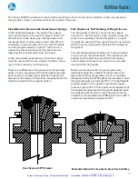
Fixed Head Vessels

Fixed head vessels are opened and closed with the 
same procedure used for removable vessels except 
that they are opened and closed with the head in 
place. Before opening the vessel lower the heater 
and swing it well to the side so that it will not be 
damaged by any materials that drip from the vessel 
as it is opened.  When closing the vessel always 
hold the cylinder until both split ring sections are in 
place to lock the cylinder to the head.

Artisan Technology Group - Quality Instrumentation ... Guaranteed | (888) 88-SOURCE | www.artisantg.com

Summary of Contents for 4590

Page 1: ...s underutilized and idle equipment along with credit for buybacks and trade ins Custom engineering so your equipment works exactly as you specify Critical and expedited services Leasing Rentals Demos...

Page 2: ...399M 4590 Micro BenchTop Reactors Operating Instruction Manual Artisan Technology Group Quality Instrumentation Guaranteed 888 88 SOURCE www artisantg com...

Page 3: ...Artisan Technology Group Quality Instrumentation Guaranteed 888 88 SOURCE www artisantg com...

Page 4: ...USE THE VESSEL 14 To open the Vessel 14 Before Closing the Vessel 14 Sealing Vessels with PTFE Gaskets 14 Sealing with Flexible Graphite Gaskets 14 O Ring Closures 14 Gas Connections 15 Pressurizing...

Page 5: ...e protection provided by the equipment may be impaired Safety Information To avoid electrical shock always 1 Use a properly grounded electrical outlet of correct voltage and current handling capabilit...

Page 6: ...ng carriers The vessel motor heater and tem perature controller may be packed separately for convenience in shipping but these parts are easily reassembled Examine the components closely for any loose...

Page 7: ...nvenient use in daily operation within certain temperature and pres sure limits using gaskets closures and other elements carefully selected for safe operation within the limits specified for that des...

Page 8: ...r Self Sealing O Ring Closure The flat gasket is held in a recess in the vessel head and a machine pilot on the cylinder closes the recess to completely contain the gasket The split ring closure used...

Page 9: ...ture since the strength of any material will normally fall off as the temperature is increased Temperature and pressure limits are also affected by the physical properties and temperature limits of th...

Page 10: ...the heater into the heater socket on the rear panel of the Series 4848 Reactor Controller 4 Plug the motor cord into the motor socket on the rear of the controller Secure the clamp on the motor cord w...

Page 11: ...id Sampling Valve The liquid sampling valve is attached to the same fitting as the gas inlet valve and connected to the same dip tube With this arrangement incoming gas is always introduced below the...

Page 12: ...under 1000 psi a relief valve is added and set to protect the gage A 1000 psi rupture disc is installed as the fail safe vessel protection For highly corrosive applications where the vapor phase might...

Page 13: ...con tinuous runs at high speeds the oiling rate should be increased to three drops per minute If the motor becomes sluggish flush it with a non flammable solvent in a well ventilated area Disconnect...

Page 14: ...Notes w w w p a r r i n s t c o m 13 Artisan Technology Group Quality Instrumentation Guaranteed 888 88 SOURCE www artisantg com...

Page 15: ...flow under the loading pressure Routinely inspect cap screws on the split ring closure for lubrication and cleanliness It is important to clean and lubricate them periodically so that the required to...

Page 16: ...t ting gas so as not to exceed the maximum working limit Remember that any subsequent increase in temperature will raise the pressure Also be sure that the amount of liquid placed in the vessel is car...

Page 17: ...in place on the head before attaching any head fittings The compres sion ring cannot be installed after fittings have been screwed into the head 8 Clean all threads and gas passages thoroughly and re...

Page 18: ...usual occurrence raises any safety questions To return a vessel for repair contact Parr Instrument Company for a return authorization number RMA Apparatus returned for testing and overhaul should be s...

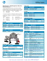
Page 19: ...lit Ring For parts made from alternate materials use the codes shown below as a suffix to the standard part number CM Alloy 400 CC Alloy 20Cb3 CT Alloy 600 CA Titanium G2 or G4 CG Alloy B 2 CH Alloy C...

Page 20: ...haft Impeller Assembly Part No Description Code A1987HC Shaft Impeller 25 50 mL SC A1987HC2 Shaft Impeller 100 mL SC A1987HC3 Shaft Impeller 25 50 mL RV A1987HC4 Shaft Impeller 100 mL RV A1987HC5 Shaf...

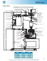
Page 21: ...C A451VB VALVE 555VBAD RED ADAPTER 154VB ELBOW A455HC S R ASSEMBLY 420HC2 ADAPTER A451VB VALVE 555VBAD RED ADAPTER 1401HC HEX RED NIPPLE A455VB2 VALVE A1120HC6 MAG DRIVE 836HC GAGE ADAPTER 593HC SERI...

Page 22: ...well 100 mL RV A2067HC5 Thermowell 25 50mL FH A2067HC4 Thermowell 100mL FH Dip Tube Part No Description Code 1443HC DipTube 25 mL 1443HC2 DipTube 50 mL 1443HC3 DipTube 100 mL Shaft Impeller Assembly P...

Page 23: ...C5 A2345HC5 1452HC12 NIPPLE HEX 1 4 NPTM ADAPTER SINGLE VALVE 1 4 NPTM DIP TUBE 50mL 2430HC19 A176VB COMPRESSION NUT SHORT SPLIT RING ASSEMBLY VALVE STRAIGHT A176VB A176VB AND LATCH HP HT ELBOW 1 4NPT...

Page 24: ...Gasket Flexible Graphite SR FG Thermowell Part No Description Code A2067HC5 Thermowell 25 50mL FH A2067HC4 Thermowell 100mL FH Dip Tube Part No Description 1443HC DipTube 25 mL 1443HC2 DipTube 50 mL...

Page 25: ...able Speed XP Explosion Proof Rated TW Thermowell HP HT High Pressure HighTemperature OVERARM PLATE OPTICAL WHEEL ENCASEMENT MOTOR RELEASE KNOB DRIVEN PULLEY BELT HUB ASSEMBLY SNAP RING ISOLATOR UPPER...

Page 26: ...SCREW 2224HC BELT GUARD STD 4 TW19NL LOCK WASHER OPTIONAL 845HC2 RELEASE KNOB 299HC2 BUSHING 328E7 HOLE PLUG A2223HC DRIVEN SHAFT ASSY 863HC COLLAR 2075HC2 COUPLING SN5013HX HEX NUT OPTIONAL A2262E T...

Page 27: ...7NL 2209HC BEARING 2187HC COUPLING FLEXIBLE SNAP RING 3 8 LOCK WASHER 4X SB1932BT06 10 32 X 3 8 BHSCS 2222HC DRIVE SHAFT 4X TW19NL LOCK WASHER 2226HC A3443HC BEARING HOUSING ASSEMBLY REF 2221HC HP VOL...

Page 28: ...4590MicroReactors w w w p a r r i n s t c o m 27 4593 Micro Reactor with Fixed Head Artisan Technology Group Quality Instrumentation Guaranteed 888 88 SOURCE www artisantg com...

Page 29: ...399M R06 01 22 15 Artisan Technology Group Quality Instrumentation Guaranteed 888 88 SOURCE www artisantg com...

Page 30: ...uipment Have surplus equipment taking up shelf space We ll give it a new home Learn more Visit us at artisantg com for more info on price quotes drivers technical specifications manuals and documentat...

Reviews: