


7
7.. To Reduce the risk of shock, this fan must be installed
by removing fuse or switching off circuit breaker.
2.. Do not use with solid state fans
3.. Electrical wire must meet all local and national
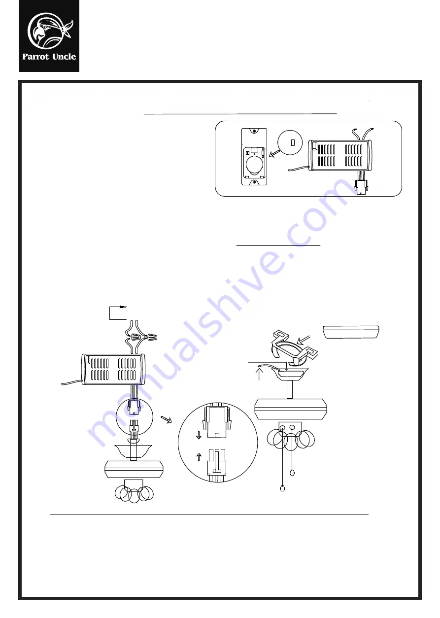
1.. INSTALLING RECEIVER IN CEILING FAN
electrical code requirements.
4.. Supply for fan must be 110/120 volt, 60Hz, 3.5A
5.. Maximum fan motor amps: 1.0.
6.. Maximum light watts: 180 incandescent or ballast and LED.
1.. WARNING: HIGH VOLTAGE! Disconnect power
INSTRUCTION OF INSTALLATION AND OPERATION
Remote controller
TRANSMITTER
(FIG.1)
White receiver wire(AC IN N)......White supply wire
Red/Black receiver wire(AC IN L)......Red/Black supply wire
supplied.
2.Remove ceiling fan canopy from the mounting bracket.
B. Installing receiver in fan
CONNECT
CONNECT
1.. Remove power from the circuit.
CAUTION: Ceiling Angle Shall Not Exceed 30 Degrees,
For Mounting Controller. Models GA030
Make connections as follows, using the wire nuts
4.
3.
3.Disconnect existing wiring between ceiling fan
and Supply in electrical junction box.
White receiver wire(TO MOTOR N)...White fan wire
Black receiver wire(TO MOTOR L)...Black fan wire
Blue receiver wire(FOR LIGHT)...Blue light wire
(FIG.3)
ANTENNA PUT AT OUTSIDE
OF CANOPY BOX CAN GET
MORE OPERATION DISTANCE
LIGHT MUST KEEP AT THE
TURN ON POSITION
FAN MUST KEEP AT THE
HIGH SPEED POSITION
RECEIVER
CANOPY
FROM POWER SOURCE
AC 110~120 VOLT
60Hz 3.5AMPS.
Use wire connecting nuts supplied with the fan.
(FIG.2)
RECEIVER
A.Safety precautions
with a wall switch/control.
CANOPY
WHITE
INPUT
RED/BLACK
OUTPUT
ANT
INSERT
BIUE
BLACK WHITE
ACN
INPUT
ACL
OUTPUT
ANT
RECEIVER
Lay the brown antenna wire on top of the receiver,and put the receiver into the mounting bracket.
b.
If other fans or supply wires are different color, have this unit installed by qualified licensed electrician.
d.Restore power.
Reinstall the canopy on the mounting bracket.
c.
Push all connected wires up into junction box.
a.
e.
e.Install 3.0 volt battery. (To prevent damage to transmitter, remove the battery if not used for a long time).
f.f. Store the transmitter away from excessive heat or humidity.
This remote control unit is equipped with roll code combinations. In order to prevent possible interference from or to
g.
other remote units such as garage door openers, car alarm or security system. If you find that your fan and light kit go on
and off without using your remote control, simply change the code combination in your transmitter and receiver
RECEIVER
CODE
CODE
COM
CODE
LEARN
TO
F830
7
Installation & Operating Instructions for the
Parrot
uncle Ow ner's Instal
lation ,Ma
nual
WARNING: SHUT POWER OFF AT FUSE OR CIRCUIT BREAKER


