INSTRUCTION REF: IN176
ISSUE No. 1
DATE 2.01.08
Page 39 of 59
TELEPHONE:
SERVICE (44) 01332 875665
FAX:
SERVICE (44) 01332 875536
Parry Group Limited,
Town End Road, Draycott, Derby, England DE72 3PT
www.parry.co.uk
WARNING
Mains voltage is present. Care must be exercised when setting potentiometers. It
is the responsibility of the user to ensure compliance with the Health and Safety
at Work Act 1974.
MOTOR PROTECTION
Fuses in the units are for protection of the controller wiring and components in
case of short circuits.
They do not afford motor overload protection.
The installer should provide motor protection as recommended by IEE
Regulations.
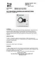
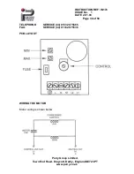
CONTROLS
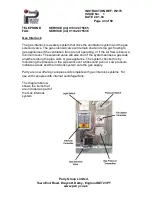
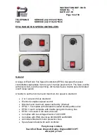
1. On/Off Switch: This isolates the motor from the live line. Live remains
present on the fuse and neutral remains present on the PCB unless a
separate isolator is fitted before the controller.
2. Front Panel Rotary Knob: This enables the user to vary the fan motor
speed from a pre-set minimum to maximum speed.
3. Minimum Speed: This internal board mounted control pot provides
minimum speed adjustment to as low as 10% of the maximum rated motor
speed.
4. Maximum Speed: This internal board mounted control provides maximum
speed adjustment. This control is provided to reduce any dead band the
motor may have.
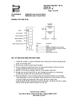
WIRING THE CONTROL
Make the connections to the control as follows:
Terminal No:
1. Supply Earth
2. Supply Live (L)
3. Supply Neutral (N)
4. Motor Neutral (NI)
5. Do not use
6. Motor Control Live (L1)

