INSTRUCTION REF: IN176
ISSUE No. 1
DATE 2.01.08
Page 51 of 59
TELEPHONE:
SERVICE (44) 01332 875665
FAX:
SERVICE (44) 01332 875536
Parry Group Limited,
Town End Road, Draycott, Derby, England DE72 3PT
www.parry.co.uk
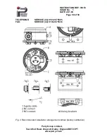
Fig.4
Horizontal installation arrangement, electrical connections upward. Actual
switching points are 11 Pa higher than the scale.
Fig. 5
Horizontal installation arrangement, electrical connections downward.
Actual switching points are 11 Pa lower than the scale.
Note
With the safety cover removed, contact with terminals 1, 2 and 3 poses a lethal C
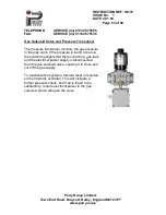
hazard (mains power voltage)! Adjusting of upper/lower switching point
(Dial B: For higher switching point [higher pressure] turn in clockwise direction.)
Allow pressure to increase gradually (do not exceed max. pressure limit), adjust
desired switching point with dial (B).
Check the upper or lower switching points by raising and lowering the pressure
several times and make any necessary adjustments.
Note!
Adjust switch within printed-on scale only!
Do not
turn the dial (B)
into the area of the black mark
! [Switching contact changes from NC
(1-2) to NO (1-2).1

