background image

Bernese Mountain Dog 

 Page 11 of 20 

Installation Instructions 


Step 5: Connect the USB-A port on the case to the battery pack (Bernese Mountain Dog G only). 

A.


This step only applies to the Bernese Mountain Dog G. 

B.


Plug the provided USB-A cord into the USB-A port on the case and the USB-A port on the battery 
pack, shown in Figure 10. 

Step 6: Connect the battery pack to the DC charging port on the case (Bernese Mountain Dog G 
only). 

A.


This step only applies to the Bernese Mountain Dog G. 

B.


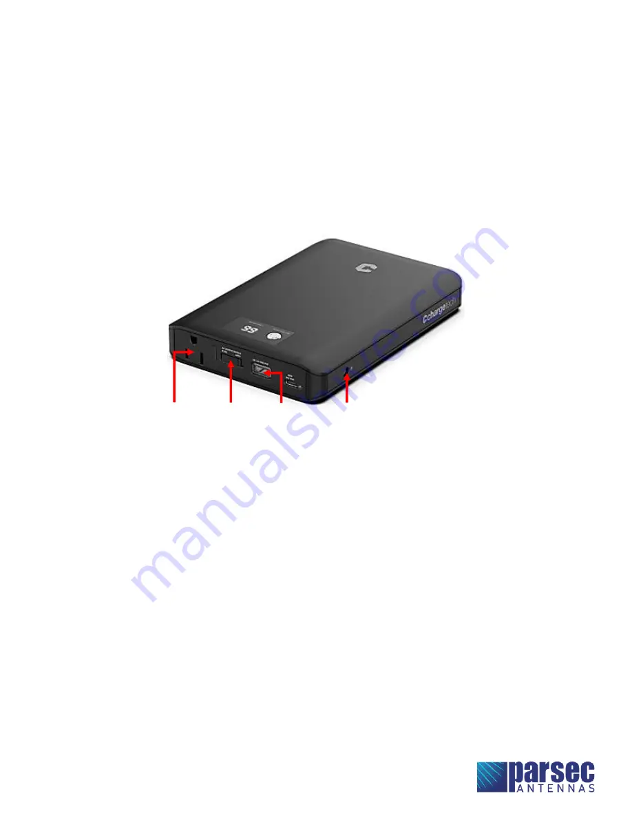
Connect the DC charging port cable from the case to the DC charging port on the side of the 
battery pack, shown in Figure 10. 


Figure 10: ChargeTech 27K Battery Pack Connections. (Bernese Mountain Dog G)


AC Outlet  AC Output 

Switch 

DC Charging 

Port 

USB-A 

Summary of Contents for Bernese Mountain Dog A

Page 1: ...ntenna works on most of the common North American LTE bands with high efficiency The Bernese Mountain Dog is optimized for LTE isolation Table of Contents Antenna Versions 2 Required Tools Accessories...

Page 2: ...ountain Dog case antenna comes in three versions A G and L with different features listed below Bernese Mountain Dog A Bernese Mountain Dog G Bernese Mountain Dog L AC Power Port 4x RJ 45 Ports USB A...

Page 3: ...Cords 4 pcs USB A Cord Battery Tray for ChargeTech 27K Battery Pack LED Display Cover Cable Ties NEMA Male to Female Adapter PTA00351 Black Oval Head Screws with Washers 21 pcs PTA0399 TL Pan Head Sc...

Page 4: ...over plate onto the battery tray and fasten with the six PTA0368 B black flat head machine screws provided in the kit as shown in Figure 2 If the battery tray does not align perfectly with the cover p...

Page 5: ...in Figure 3 D For R1900 router align the router with the holes on the cover plate Mount the router using the four PTA0579 pan head screws and four PTA0604 lock nuts provided in the kit as shown in Fi...

Page 6: ...Bernese Mountain Dog Page 6 of 20 Installation Instructions Connection Figure 5 Connection Diagram for Bernese Mountain Dog A L...

Page 7: ...Bernese Mountain Dog Page 7 of 20 Installation Instructions Figure 6 Connection Diagram for Bernese Mountain Dog G...

Page 8: ...ables and images below Cradlepoint IBR900 with COR Extensibility Dock Cradlepoint R1900 Antenna Cable Router Terminal Antenna Cable Router Terminal LTE 1 MAIN0 on modem on dock LTE 1 MAIN LTE 2 AUX0 o...

Page 9: ...emale adapter provided in the kit B For Bernese Mountain Dog A L plug the NEMA male to female adapter into the AC power port on the case C For Bernese Mountain Dog G plug the NEMA male to female adapt...

Page 10: ...N ports and WAN port on the router shown in Figures 7 and 8 C Connect the other ends of the ethernet cords from the router to the RJ 45 ports on the case Keep track of which cord is connected to the W...

Page 11: ...case and the USB A port on the battery pack shown in Figure 10 Step 6 Connect the battery pack to the DC charging port on the case Bernese Mountain Dog G only A This step only applies to the Bernese...

Page 12: ...nection and ensure that no connections are loose B Use cable ties or other wire management to neatly bundle the cables Pack the cables neatly inside the bottom half of the case Ensure that the antenna...

Page 13: ...Bernese Mountain Dog Page 13 of 20 Installation Instructions Figure 12 Fully Connected 9in1 Bernese Mountain Dog G with Cradlepoint IBR900 Router and COR Extensibility Dock...

Page 14: ...Bernese Mountain Dog Page 14 of 20 Installation Instructions Figure 13 Fully Connected 9in1 Bernese Mountain Dog L with Cradlepoint IBR900 Router and COR Extensibility Dock...

Page 15: ...plate onto the bottom half of the case Ensure that no cables are pinched between the cover plate and the case B Fasten the cover plate to the case using the twenty one PTA0351 black oval head screws...

Page 16: ...case B For Bernese Mountain Dog G follow steps 2C 2G below C Turn the battery pack ON by pressing and holding the power button for 3 seconds The display on the battery pack will indicate the battery p...

Page 17: ...he LAN ports on the router Step 4 Login to Cradlepoint NetCloud A Open a web browser on the computer and type 192 168 0 1 into the address bar This will bring up the Cradlepoint NetCloud login shown i...

Page 18: ...INTERNET and then CONNECTIONS B In the Device List table select the option with a cellular SIM as shown in Figure 17 Figure 17 Select the device with a cellular SIM in Cradlepoint NetCloud Antenna set...

Page 19: ...us mode and the entire unit will stay ON until manually turned OFF F While plugged in and charging the battery pack will allow pass through charging to continue powering any devices that are plugged i...

Page 20: ...is within 24 inches of the antenna Install the antenna or mast assembly on a windy day Install the mast close to power lines as it can cause serious injuries or death WARNING This document gives the...

Reviews: