background image

7300w² Monitor Instruction Manual

1  Foreword

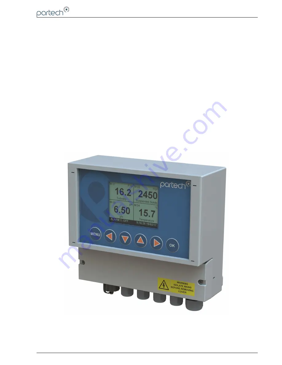
7300w² Monitor is the “Operator Interface” to the WaterWatch² family of measuring instruments and sensors,
and has been developed to be the successor to the very popular WaterWatch'1' and 7200 Monitors. Using
the latest embedded processor technology, the 7300w² Monitor has been designed to encompass an easy to
use and intuitive interface while providing advanced features and communication protocols to satisfy the
most demanding of applications and environments. 

The  7300w²   Monitor  is   the   key   to   the   WaterWatch²   product   range.  The  7300w²   Monitor  is   designed   to
interface with all sensors in the WaterWatch² family. These sensors can be easily identified by the w ² in the
product name. 

The standard 7300w² Monitor provides connectivity for 1 or 2 sensors. Up to 8 sensors can be added to a
single 7300w² Monitor using optional “Expansion Boxes”. Further interfaces are available to add flexibility to
the 7300w² Monitor by adding additional terminations, supplementary power supplies, modems or extended
communication options, including PROFIBUS, Ethernet or MODBUS.  

Combining   different   sensors   on   a   single   monitor   provides   a   very   cost   effective   way   of   simultaneously
monitoring parameters such as Dissolved Oxygen and Suspended Solids in an Activated Sludge Plant or pH
and Turbidity at a treatment works outfall on a single user interface. As processes change, or demands
increase, sensors can be added at a later date saving costs and reducing redundancy.  

In an ever demanding world, the 7300w² Monitor is the only choice if you need to keep on budget without
compromising functionality or reliability while maintaining a future proof philosophy. 

224081IM Issue 22  Issue Date 27/03/2018

`

Page 5 of 46

Summary of Contents for 7300w2 Monitor

Page 1: ...INSTRUCTION MANUAL 7300w Monitor Issue 22 ...

Page 2: ...7300w Monitor Instruction Manual This page is intentionally left blank Page 2 of 46 224081IM Issue 22 Issue Date 27 03 2018 ...

Page 3: ...Navigation 17 4 1 1 Menu Button 17 4 1 2 Navigation Buttons 17 4 1 3 OK Button 17 4 2 Default Configuration 17 4 2 1 Electrodes Sensors and Measurements Definition 17 4 3 Measurement Display Mode 17 4 3 1 Trending Display Mode 18 5 System Configuration 19 5 1 Monitor Config Menu 19 5 1 1 Bleeper 19 5 1 2 Backlight 20 5 1 3 Contrast 20 5 1 4 Language 20 5 1 5 Set Time Date 20 5 1 6 Enable Service M...

Page 4: ...9 1 Logging Status 33 5 9 2 Download Logged Data to USB 33 5 9 3 Logging Interval 33 5 9 4 Logging Mode 33 5 9 5 Logging Reset 33 5 9 6 Locating the Log File 33 6 Service Mode 35 6 1 Access to Service Mode 35 6 1 1 Enable Factory Mode 35 6 1 2 Monitor Config Adv 35 6 1 3 Output 0 4mA and 20mA Offset 36 7 Menu Tree 38 8 Maintenance 40 8 1 On Board Battery Backup Replacement 40 9 Faults 41 9 1 Monit...

Page 5: ...ctivity for 1 or 2 sensors Up to 8 sensors can be added to a single 7300w Monitor using optional Expansion Boxes Further interfaces are available to add flexibility to the 7300w Monitor by adding additional terminations supplementary power supplies modems or extended communication options including PROFIBUS Ethernet or MODBUS Combining different sensors on a single monitor provides a very cost eff...

Page 6: ...to the installer ELECTRICAL CAUTION Used where there is a danger of electric shock to the installer or end user or where caution is required to prevent damage to the instrument MAINTENANCE NOTES Used to highlight recommended maintenance procedures and help with fault finding ENVIRONMENTAL NOTES General notes on environmental issues waste and disposal 2 2 WaterWatch Trademark WaterWatchw is the fam...

Page 7: ...ring regulations and standards refer to BS7671 for UK installations Please check the correct voltage is applied to the monitor before making live Incorrect supply voltage can cause damage to the 7300w Monitor Only connect sensors from the w range to this monitor other Partech products without the w reference are not compatible and may cause damage if connected IF IN DOUBT PLEASE ASK Never work on ...

Page 8: ...carried out by a Partech engineer Partech can provide a service contract for your system Please ask for details 3 5 End of Life Disposal This equipment should be recycled according to local regulations Partech can provide recycling and disposal of your old Partech equipment and may also provide the same service for other manufacturers equipment when replaced with Partech equipment Partech may prov...

Page 9: ...ll heights If the sensor is to be calibrated by a single person consideration should be paid to the proximity of the monitor to the sensor Some sensors require constant monitoring or staged inputs during the calibration process This could be difficult if the sensor is remote from the monitor Keep the monitor out of direct sunlight This can make the display difficult to read and in extreme conditio...

Page 10: ...nging bracket moulded into the back of the monitor Loosen the screw if too tight to hang Remove the lower terminal strip cover to reveal the two lower fixing slots shown as A on the illustration below Level the Monitor with a spirit level and mark the two lower slots Remove the enclosure and fix drill tap the above marks Rehang the enclosure Tighten the top screw if the enclosure feels loose and f...

Page 11: ...uration Left 1 x USB connection Centre 4 x M16 glands 4 5 10mm Ø cable Right 1 x M20 gland 5 10mm Ø cable Gland holes are clearance not tapped Always blank unused glands to retain the IP rating of the enclosure Cabling When selecting and calculating the mains power cable please note an ambient temperature of 60ºC may see a rise to 80ºC within the terminal compartment This should be considered when...

Page 12: ...wered 7300w Monitor is powered typically from a 100VAC to 240VAC 50 60Hz supply Min Max voltages are 85VAC to 264VAC 47Hz 63Hz We do not advise operating the monitors in the field at voltages approaching the Min or Max values as surges dips or ripples in supply can fall outside the Max Min limits and can cause damage or interruptions to the performance of the 7300w Monitor The supply voltage shoul...

Page 13: ...ck Term 2 Illustration Left shows drain wire and Black wire connected together and covered in Black Heat shrink Always use Bootlace ferrules when terminating the sensors to ensure a good connection to the terminals 4 4 5 Extending Sensor Cables Sensors are usually supplied with 10m cables longer cables can be provided on request These cables can be extended to a maximum length of 100m To ensure op...

Page 14: ...nd N O will be Closed Circuit During an Alarm condition system fault or power failure the relay will de energise returning back to the state illustrated on the label If the alarm has not been configured the relay will remain de energised 4 4 7 Analogue Outputs The 7300w Monitor provides the user with two 0 4 20mA analogue outputs The Analogue outputs are connected to the 4 way terminal strip locat...

Page 15: ...r the 7300w and the same precautions apply NOTE Once the Expansion Boxes have been wired unplug each 4 way connector from the 7300w Monitor before powering up the unit The system must recognise each box in turn through the ModTechw Protocol Add Expansion Config Menu Similarly disconnect all Sensors from the Expansion Box before power up see Add Sensor Config Menu When using 8x Sensor Input Expansi...

Page 16: ...7300w Monitor Instruction Manual Example of a typical 8x Input and 8x Output Expansion Box installation Page 16 of 46 224081IM Issue 22 Issue Date 27 03 2018 ...

Page 17: ...measurement must be configured before a value is displayed 5 2 1 Electrodes Sensors and Measurements Definition Throughout the WaterWatch product range the terms Electrode Sensors and Measurement will be used in the following manner Electrodes this applies to the measuring element such as a pH electrode often the replaceable or consumable part of a sensor Sensors this term applies to a physical de...

Page 18: ...he trending chart Press the or to scroll back and forth in time Press or to zoom in and out on the time axis Press once again to enable scrolling and zooming on the measurement axis Press the or to zoom out and in on the measurement axis respectively Press or to move up or down the measurement axis Press to return to the main trending window Page 18 of 46 224081IM Issue 22 Issue Date 27 03 2018 ...

Page 19: ...des access to some advanced configuration and reset functions From the MAIN MENU ensure MONITOR CONFIG is highlighted if not press or to highlight the option then press 6 1 1 Bleeper From the MONITOR CONFIG menu press or to select BLEEPER The bleeper button pressed acknowledgement bleep can be turned on or off as desired Under normal circumstances it is preferable to leave the bleeper turned on as...

Page 20: ...e factory default setting is English Press or to highlight the option required and press to select A tick will appear next to your selection Press to exit this option 6 1 5 Set Time Date From the MONITOR CONFIG menu press or to select SET TIME DATE 1 Press or to move the cursor below the digit to be changed Press or to increase or decrease the digit Press to accept Daylight Savings The monitor doe...

Page 21: ...and 4 x Relay Outputs These boxes must be installed and configured individually before use The configuration only applies to the Output and Alarm features the sensors will be found by the ModTechw Protocol in the Sensor Config Menu 1 After power up plug in the first expansion box 2 From the MAIN MENU screen select EXPANSION CONFIG by pressing or and press 3 The EXPANSION MENU is displayed Press to...

Page 22: ...red OUTPUT COMM FAIL and RELAY COMM FAIL states as explained in the relevant Output and Alarm sections E 0 Output Comm Fail This is the default condition the analogue outputs will be forced to in the event of a communication error with the monitor Condition options include 0mA 4mA 20mA or Hold last good value E 0 Relay Comm Fail This is the default condition the relay outputs will be forced to in ...

Page 23: ...ration that is similar to a sensor Therefore to add this box to the 7300w Monitor go to the Sensor Config menu and select Add Sensor The monitor will scan the Modbus addresses and will find PN224920 at Modbus address 39 If multiple boxes of the same type are to be added then please change the Modbus address to a free number as explained in other parts of this manual As part of the sensor addition ...

Page 24: ...ayed 6 3 1 Sensor Status This menu will display a list of sensors installed and will include the serial number for reference Up to 8 sensors can be configured to a single monitor If only one sensor is installed the remaining seven sensor allocations will display Disabled 6 3 2 Add Sensor 1 After power up plug in the first Sensor 2 From the MAIN MENU screen select SENSOR CONFIG by pressing or to hi...

Page 25: ...c term to describe the address of each sensor and Expansion Box on the ModTechw network If two or more sensors of the same type are to be installed then once the first sensor has been configured it will be necessary to change it s Modbus Address before connecting a second sensor If only one sensor is to be connected to the 7300w monitor or several sensors of different types it is not necessary to ...

Page 26: ...he user to configure A single sensor may only provide a single measurement e g Turbidity or multiple measurements e g DO and Temperature Each measurement may also be offered in different formats e g FTU or mg l for Turbidity All available measurements and formats will be displayed under the Measurement Config Menu denoted by M01 to M0x Further information on the configuration operation and calibra...

Page 27: ...to the measurement will also be removed 6 4 Measurement Specific Config Selecting the measurement in the MEASUREMENT CONFIG menu will display a new sub menu associated with that particular parameter This will be specific to the measurement of interest The menu explanation in this manual is limited only to Display Position For a full explanation of this sub menu see the instruction manual accompany...

Page 28: ...rtant Without a measurement allocated to an alarm a limited selection of options will be displayed in Alarm Config Once a measurement has been allocated then a more complete selection will be available See screenshots left From the MAIN MENU select ALARM CONFIG and press 1 Highlight the Alarm output to be configured e g ALARM 5 E 1 and press 2 Highlight MEASUREMENT using or and press 3 A list of y...

Page 29: ... falls below 50mg l during the 10 seconds delay the timer will reset Reset Delay The reset delay is the opposite to the Set Delay whereas the reading must remain below the set point value for the duration of the delay before the alarm will reset Test This menu option is for diagnostics use and allows the operator to test the alarm relay by forcing the relay ON OFF Press or to switch the relay ON O...

Page 30: ...en selected Press to return back to OUTPUT 5 E 1 Config menu 5 The OUTPUT 5 E 1 Config menu will now display all the options available to configure the output 6 Listed below are the descriptions of each option Configure as required Measurement The selected measurement as configured above Type Offers the following options 4 20mA Gives 4 20mA output signal 0 20mA Gives 0 20mA output signal OFF Switc...

Page 31: ...gue output 1 within the monitor Output 2 M Config Analogue output 2 within the monitor When an Expansion Box is connected to the 7300w Monitor additional configurable analogue outputs are added to the list in the Output Config Menu as follows Output 1 E 1 Config Analogue output 1 within Expansion Box 1 Output 2 E 1 Config Analogue output 2 within Expansion Box 1 Output 3 E 1 Config Analogue output...

Page 32: ... and press This screen requests the OLD password The factory default setting is 1000 Press or to move the cursor below the digit to be changed Press or to increase or decrease the digit Press to accept You will then be asked to enter the new Password Repeat the above procedure to set the new password Password is now set 6 8 3 Set Auto Lock Two modes of Lock Instrument are available and are configu...

Page 33: ...nd status The 7300w Monitor can be set to log between once a second and once per hour The 7300w That gives a logging range of just under 3 hours to 416 days The 7300w Monitor will store the information in 6 9 4 Logging Mode There are three modes available 1 Continuous In this mode the 7300w Monitor will always log and store the latest data When the memory is full it will overwrite the oldest data ...

Page 34: ... Abbreviation Meaning MV Measurement Value MS Measurement Status SS Sensor Status For details on decoding the status columns please contact Partech support Page 34 of 46 224081IM Issue 22 Issue Date 27 03 2018 The logfile is in a CSV Comma Separated Variable format It is intended to be opened in a standard spreadsheet application e g Microsoft Excel or Open Office Calc Opening the file should resu...

Page 35: ... 7300w menus therefore a simplified notation is used in this section For example Main Menu Monitor Config Bleeper ON 7 1 Access to Service Mode Enable Service Mode as follows Main Menu Monitor Config Enable Service Mode Password 00037 You will notice that the top line of the display is now in reverse white on black text and SM Service Mode is displayed in the top left corner Exit Service Mode as f...

Page 36: ...d for 60 mins before resetting 8 240 Minutes Once set to HOLD the outputs will hold for 240 mins before resetting 9 Never Will hold outputs indefinitely Must be manually reset Once enabled the HOLD OUTPUTS menu will appear at the beginning of the MAIN MENU Once configured select HOLD OUTPUTS You will then be asked for a password This password is the same password as configured for LOCK CONFIG The ...

Page 37: ... 20mA Offset First set the 4mA offset Adjustment of the 4mA output will also effect the 20mA output i e increasing the 4mA output by 0 5mA will also add 0 5mA to the 20mA output Once the 4mA output has been adjusted as required the 20mA can then be adjusted if required 224081IM Issue 22 Issue Date 27 03 2018 Page 37 of 46 ...

Page 38: ...g Hold Output Timeout Enter Bootloader Mount USB Memory Expansion Config Expansion Status Add Expansion E WW EB 8A 8R E Remove E Modbus Addressing E Comm Fail Timeout E Output Comm Fail E Relay Comm Fail Sensor Config Sensor Status Add Sensor S 01 Sensor Type Option Measurement Config Measurement Status Add Measurement M 01 Measurement Option S 01 Alarm Config refers to 1 8 alarms available depend...

Page 39: ...formation Diagnostics Monitor Info Anybus Info Sensor Get Debug Download Debug Log Download Modbus Log User U8 Values User U16 Values User U32 Values User S32 Values Factory U8 Values Factory U16 Values Factory U32 Values Factory S32 Values Diagnostic Download Menu Tree Debug Text Output Debug RS485 Sensor Type Summary Lock Config Lock Monitor Change Password Set Auto Lock Logging Logging Status D...

Page 40: ...tor is isolated or disconnected from HAZARDOUS LIVE voltages before access 2 Remove the four plastic caps located on the corners of the display using a small flat bladed screwdriver to reveal the screws 3 Unscrew the four screws and gently lower the panel Take care as the display is connected to the back board via a ribbon cable 4 With the display panel turned over and hanging upside down by the r...

Page 41: ...the end of the message The 1 refers the to the fault state of the monitor s operating system and is not an indication of the number of the measurement at fault nor the number of sensors which are not communicating properly Before reacting to this message please observe the monitor for a few minutes The nature of the ModTechw protocol being used for communication between the monitor and sensors wil...

Page 42: ... application 11 1 Returning Equipment for Repair If equipment needs to be returned to Partech for repair or service the following address should be used SERVICE DEPARTMENT PARTECH INSTRUMENTS ROCKHILL BUSINESS PARK HIGHER BUGLE ST AUSTELL CORNWALL PL26 8RA UNITED KINGDOM Please include the following information with the returned equipment Also ensure that sensor is clean and adequately protected f...

Page 43: ...bossed 20mm dia Buttons 12 3 Electrical Operation Voltage 100 to 240VAC 50 60Hz or 12 to 24VDC Power Rating 0 8A AC 30W DC Power consumption may increase for 2 or more sensors Terminal Wire Size Max 2 5mm cores Analogue Outputs 0 4 20mA Max load 750 ohms Digital Relay Outputs 3 Reduced to 1 Relay for PROFIBUS Relay Type SPCO Max 230VAC Switching Voltage Relay Rating Max 5A 30VDC 230VAC Auxiliary C...

Page 44: ...160 226161 223162 223163 Is in conformity with the standards noted below EN 61326 2008 Electrical equipment for measurement control and laboratory use EMC requirements BS EN 61010 1 2001 IEC 61010 1 2001 Safety Requirements for electrical equipment control and laboratory use Following the provisions of European Directives 2004 108 EC EU EMC Directive 2006 95 EC Low Voltage Directive Roger Henderso...

Page 45: ...7300w Monitor Instruction Manual 224081IM Issue 22 Issue Date 27 03 2018 Page 45 of 46 ...

Page 46: ...Partech Instruments Rockhill Business Park Higher Bugle St Austell Cornwall PL26 8RA UK Tel 44 0 1726 879800 Email info partech co uk Web www partech co uk ...

Reviews: