P
AGE
16
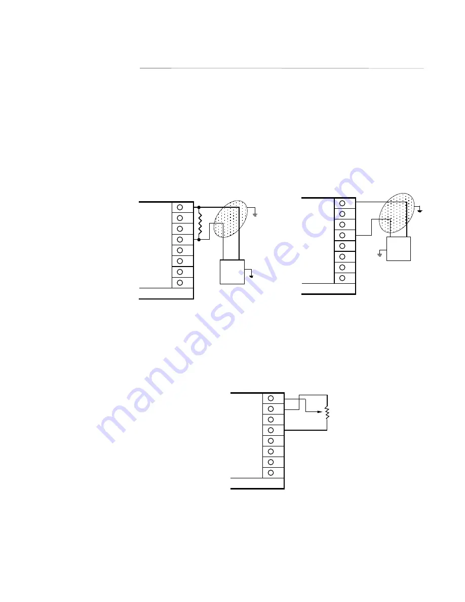
FIGURE 2-10
Remote Setpoint Input - VDC and mADC and Potentiometer
Input connections are illustrated below. Terminal 8 is positive and terminal 5 is negative.
The remote setpoint input can be configured for either 0 to 5VDC or 1 to 5 VDC input. Make
sure that the voltage input matches the voltage configuration selected in the Program mode.
For mA inputs, a 250 ohm shunt resistor must be installed between terminals 5 and 8. For
remote setpoint using a potentiometer, JU1 on options board must be in MM/PP (see page 66
and 67).
CURRENT DC REMOTE SETPOINT
8
7
6
5
4
3
2
1
-
+
MILLIAMP
SETPOINT
SIGNAL
250 OHM
SHUNT
RESISTER
NEEDED
Rear View
Shielded Twisted Pair
VOLT DC REMOTE SETPOINT
VOLT DC
SETPOINT
SIGNAL
5VDC
MAXIMUM
8
7
6
5
4
3
2
1
-
+
Rear View
Shielded Twisted
Pair
POTENTIOMETER
150 ohm to
10 K ohm
8
7
6
5
4
3
2
1
Rear View


