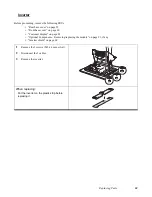
Safety and precautions
57
C
HAPTER
5
R
EPLACING
F
IELD
R
EPLACEABLE
U
NITS
(FRU
S
)
This chapter provides instructions for replacing FRUs. The following topics are described.
• “Safety and precautions”
• “Before you begin” on page 58
• “Replacing Parts” on page 58
• “Rear base cover” on page 59
• “Front base cover” on page 60
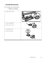
• “Front USB PCB and bracket” on page 61
• “Customer display” on page 62
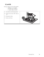
• “HDD” on page 63
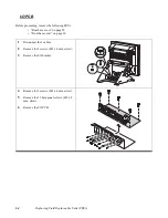
• “I/O PCB” on page 64
• “CF card PCB” on page 65
• “CF card bracket” on page 66
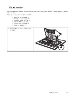
• “CPU and heatsink” on page 67
• “Inverter shield” on page 68
• “Inverter” on page 69
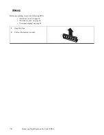
• “Memory” on page 70
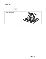
• “Video PCB” on page 71
• “Touch panel” on page 72
• “Mainboard” on page 75
• “Touch control PCB” on page 74
• “Front display cover” on page 76
• “LCD panel” on page 77
Safety and precautions
Computer components and electronic circuit boards can be damaged by discharges of static electricity. Working on
computers that are still connected to a power supply can be extremely dangerous. Follow these guidelines to avoid
damage to the computer or injury to yourself.
•
Always disconnect the unit from the power outlet.
•
Leave all components inside the static-proof packaging that they ship with until they are ready for installation.
•
After replacing optional devices, make sure all screws, springs, or other small parts are in place and are not left
loose inside the case. Metallic parts or metal flakes can cause electrical shorts.
NOTE
For instructions on how to remove and/or replace optional components includ-
ing the MSR, i-Button, fingerprint reader, and keyboard, refer to the Appendix.
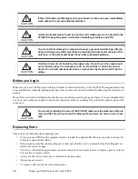
CAUTION
Only qualified personnel should perform repairs on the PT-6900. Damage due to
unauthorized servicing is not covered by the warranty.
Summary of Contents for PT-6900
Page 1: ...PT 6900 Service Manual...
Page 2: ......
Page 7: ...v List of Parts FRUs 92 Display Parts and Cables 94...
Page 8: ...vi...
Page 10: ...viii...
Page 16: ...6 Getting Started...
Page 38: ...28 BIOS Setup Utility...
Page 52: ...42 Installing Drivers and Software 5 When installation is completed click Finish...
Page 66: ...56 Locating the Problem...
Page 83: ...Replacing Parts 73 6 Remove the touch panel 7 Remove the waterproof seal...
Page 88: ...78 Replacing Field Replaceable Units FRUs...
Page 96: ...86 Appendix Optional Components Exploded Diagram and Parts List...
Page 106: ...96 Appendix Optional Components Exploded Diagram and Parts List...


