Ignition system
The ignition sys-
tem is complete-
ly sealed and has
no moving parts.
It is insensitive to
moisture and
dirt. It is desig-
ned so that the
ignition point
never needs to
be adjusted.
The Partner K950 and K1250 Active feature a built-in
over-revving protector in the electronic module, limiting
engine speed to 9,750 rpm.
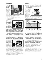
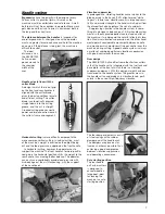
The ignition
system con-
sists of the pri-
mary coil (A)
and the secon-
dary coil (B),
both of which
surround the
iron core (C).
A transistorised
electronic mod-
ule (D) deals
with the contact-breaking function.
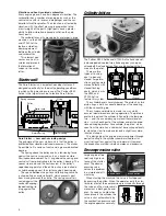
Current is generated in the primary coil when the fly-
wheel’s permanent magnet passes the coil and produces
the voltage sequence shown in the diagram below.
(The dotted line shows the voltage which is generated if
the current is not broken.)
The ignition point is determined by the electronic
module which senses variations in voltage in the primary
coil and cuts the current at the right level, at the same
time as the piston is just below top dead centre. At the
instant that the contact is broken, voltage in the primary
coil rises from 5 V (volts) to about 200 V through a pro-
cess of induction.
In the secondary coil, a high tension of about 20,000
volts is conveyed to the spark plug.
Silencer
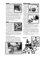
The silencer is of the single-
chamber type and the
exhaust gases are directed
towards the side – away
from the operator. The
panel between the cylinder
and carburettor cools the
exhaust port.
Most of the sound from
the machine comes from the
escaping exhaust gases.
The air filter system acts as an effective intake damper
and goes a long way to reducing sound pressure since
the intake air is not drawn from above the engine. Sound
levels are measured according to the CE norm in two ways:
– Sound pressure, measured at the operator’s ear.
– Sound level, the mean value of the acoustic power
which the machine generates, measured at twelve points
around the machine on a reflective flooring material
(concrete). These measurements are taken at idling
speed and maximum speed.
See the technical specifications on page 11.
Clutch
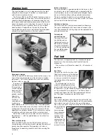
The clutch located between
the engine and the cutter is
of the centrifugal type. At
idling speed, the clutch
shoes are held against the
centre by a spring. This
means that the cutter disc
is at a standstill when the
machine runs at idling
speed. As the engine in-
creases speed, the spring
can no longer hold the shoes in place, and the shoes are
pushed against the clutch drum by centrifugal force.
Engagement speed is about 3400 rpm. At normal oper-
ating speed, centrifugal force is so high that a sudden
overload on the cutter disc will cause the belt to slip
against the pulley.
Self-lubricating clutch bearing
The clutch bearing on the K950 and K1250 Active is
lubricated automatically – a tried and tested Partner
speciality. A duct in the crankshaft opens out at the
clutch bearing. The over-pressure which is created in
the crankcase is transferred to the clutch bearing and
keeps the bearing clear of incoming dust particles and
at the same time lubricates it.
5
Electronic
circuit
breaker
STOP
control
Volts
+
-
0
Ignition
point
S
N
S
N
1
1
A
D
B
C
2
2
3
3
A
B
C
D
Ignition system
principle


