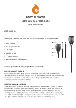
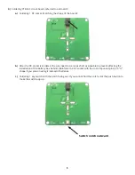
background image


c.)

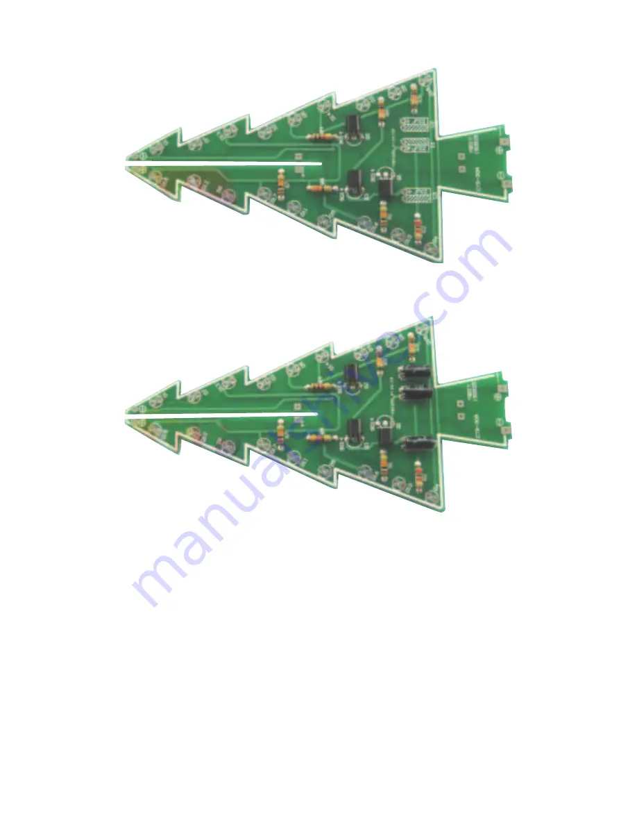
  Solder 3 transistors, bending the components before soldering (otherwise they won’t be able to lay flush 


if soldered first). Make sure to match the shape of the transistors to the shape printed on the board.
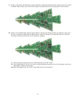
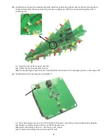
 

d.)

  Solder 3 +47uF electrolytic capacitors (bending the components before soldering, otherwise, they won’t 


be able to lay flush if soldered first). Make sure to match the shape to the printed shape on the board. 


The long terminal is positive, the short terminal is negative.
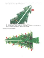
i.)

  First estimate the capacitor pin from which position to do 90 ° bend
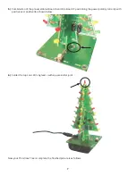
ii.)

  After folding the pin, insert it into the corresponding hole (pay attention to the installation direction, 


matching the shape of the board).
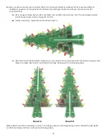
iii.)

 Bend the capacitor pin 90° in the correct direction and then solder it

2

Summary of Contents for 320-291

Page 1: ...e starting the assembly of the Christmas Tree Kit Assembly process 1 Soldering Christmas Tree circuit board abbreviated as Board A Identify A by finding the 2PH88566A or the Tree with the slot starting from the top Match the color code on the pictures with the correct resistors a Solder Brown black orange 10K resistors R1 R3 R5 R7 b Solder a Red Black Red resistor to R2 a Brown Black Red to R4 and...

Page 2: ...soldering otherwise they won t be able to lay flush if soldered first Make sure to match the shape to the printed shape on the board The long terminal is positive the short terminal is negative i First estimate the capacitor pin from which position to do 90 bend ii After folding the pin insert it into the corresponding hole pay attention to the installation direction matching the shape of the boar...

Page 3: ...and the long pin of LED is positive i First estimate the LED pin from which position to do 90 bending ii After folding the pin insert it into the corresponding hole pay attention to the installation direction iii Bend the LED pin 90 in the correct direction and then solder it The soldering of Board A is completed 3 ...

Page 4: ...red The remaining resistors locations are brown black orange R1 R3 R5 b Solder transistors capacitors and LEDs like board A c After Board A and Board B are soldered you can power on to test whether the two boards can glow and flicker normally After both A and B flash normally continue with the following steps After boards A and B are soldered connect to a voltage of about 4 5V respectively confirm...

Page 5: ...eed to be cut as short as possible to prevent affecting the installation of the battery box behind Reinforce the DC socket with the cut component pins in a U shape if you plan on using it instead of batteries c Soldering 1 key switch with the notch facing out If you cannot find the notch click the push button to make the switch pop up 5 Switch notch outward ...

Page 6: ...irst ii Solder the two boards with tin wire iii The positioning arrows of board A and board B are shown in the enlarged picture on the upper left e Combination of the battery box and Board C i Pass the battery box wire out of the bottom of board C according to the corresponding polarity ii Reserve a certain length of wire cut off the excess wire iii Solder the battery box wire matching red black i...

Page 7: ...rd A and B to Board C positioning the power polarity correctly with positive over positive like shown below 6 Solder the top one LED long lead with square solder joint Now your Christmas Tree is complete the finished picture is as follows 7 ...

Page 8: ...ns Working voltage DC4 5 5V Power supply 3 AA batteries or 5 VDC USB power Dimension 2 36 x 2 36 x 5 35 60mm 60mm 136mm Two power supply methods 1 3 AA batteries sold separately 2 External 5 VDC USB A power supply port sold separately 3 AA batteries Power indicator Power switch External 5V power supply 8 ...

Reviews: