background image

www.parweld.com

6

3.0 technical 

Specifications

The XTM 503si, Is a compact type machines with integrated wire 
feed units for use with three phase 400V supply. The machine uses 
inverter technology to allow MIG , TIG and MMA welding to be 
performed.

Feature

XtM503Si

Input voltage

400V +/-10%

Hz

50/60

phases

3

Wire drive

4 roll

Current Draw (a)

41.8

rated input 

capacitance  KVa 

27.5

No-load voltage                 

V

73V

Rated working 

voltage V

16-39

MIG welding current           

a

40-500

Fuse Rating

(a)

32

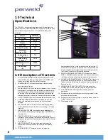
4.0 Description of Controls

1.  VOLTAGE DISPLAY INDICATOR: It will be display Arc-Force 

preset in MMA, and display voltage preset in MIG/MAG, and 

display real-voltage when the welder is working. 

2.  POWER INDICATOR: When the machine is turned on, the 

power indicator will be on.

3.  ALARM INDICATOR: When the thermal indicator is on, it shows 

the machine is overloaded  and the internal temperature is too 

high. Weld output will turn off automatically but the fan will still 

be working. When the internal temperature is decreased, the 

overload light will turn off and the machine will be ready to weld

4.  OUTPUT INDICATOR, when illuminated the output power is on.
5.  CURRENT/WIRE SPEED DISPLAY displays the wire feed 

speed or the welding current depending upon the feature 

selected.

6.  LEFT ADJUST KNOB: Its main function is adjusting welding 

current in MMA mode; and the final current setting in 4T mode 

(craterfill) 

7.  MIDDLE ADJUST KNOB: Its main function is adjusting Arc-

Force in MMA, and adjusting welding voltage in MIG/MAG. for 

the crater fill.

8.  RIGHT ADJUST KNOB: Its main function is adjusting the 

inductance in MIG welding, low inductance allows the current to 

surge during dip transfer, high inductance gives stability during 

spray transfer.

9.  MIG MODE SELECTOR, this button toggles between the 

Manual MIG Welding mode and the synergic MIG welding 

mode. 

10.  TRIGGER MODE. 2T operation is when the trigger is 

depressed and held in for the duration of the welding cycle. 4T 

mode allows the trigger to be pressed and released. At the end 

of the weld pressing the trigger in again and holding activates 

the Craterfill current until the trigger is released.

11.  WELD FUNCTION SELECTION BUTTON: Users can select 

MMA  or MIG/MAG function by this button, and the indicators at 

the left part of button will indicate the selection weld function.

12.  MIG/MIG WIRE DIAMETER SELECTION BUTTON:  Users can 

select wire diameter by this button, and the indicators at the 

left part of button will indicate the selection wire.(only applies in 

Synergic mode)

13.  MIG/MAG GAS SELECTION BUTTON: Users can select 

shielding gas by this button. (only applies in Synergic mode)

14.  GAS PURGE BUTTON, purges the shielding gas when 

depressed. 

15.  Remote control for the Welding current (synergic mode) or the 

wire speed (manual mode)

16.  Remote control for the arc /-( synergic mode) or the Arc 

Voltage (manual mode) 

17.  Wire loading button

1
2
3
4

9
10
11

5

6
7
8
12
13
14

15

16

17

18

Summary of Contents for XTM503Si

Page 1: ...Operator Manual ISSUE 1 XTM503Si ...

Page 2: ...per maintanance this equipment should provide years of reliable service All our systems conform to ISO9001 2000 and are independently audited by NQA The entire product range carries the CE mark and is constructed in accordance with European directives and the product specific standards where they apply Further Information Parweld is the UK s leading supplier of MIG TIG and Plasma torches and consu...

Page 3: ...5 Changing drive roll sets 7 5 6 Welding wire installation 7 5 7 torch installation 8 5 8 Work return lead connection 9 5 9 Shielding gas connection 9 6 0 Operation 9 6 1 Feeding wire electrode 9 6 2 Spot Weld Mode 9 6 3 Optimising weld parameters 9 7 0 Fault finding 10 8 0 Accessories 11 8 1 Drive rolls 11 8 2 Torch spares 12 8 3 Gas equipment 13 9 0 EC declaration of conformity 14 9 1 RoHS Compl...

Page 4: ... manual Wear a safety harness if working above floor level Keep all panels and covers securely in place Clamp work cable with good metal to metal contact to work piece or worktable as near the weld as practical Insulate work clamp when not connected to work piece to prevent contact with any metal object Welding produces fumes and gases Breathing these fumes and gases can be hazardous to your healt...

Page 5: ...fect pacemakers Pacemaker wearers keep away Wearers should consult their doctor before going near arc welding gouging or spot welding operations NOISE can damage hearing Noise from some processes or equipment can damage hearing Wear approved ear protection if noise level is high Shielding gas cylinders contain gas under high pressure CYLINDERS can explode if damaged Protect compressed gas cylinder...

Page 6: ...ng in 4T mode craterfill 7 MIDDLE ADJUST KNOB Its main function is adjusting Arc Force in MMA and adjusting welding voltage in MIG MAG for the crater fill 8 RIGHT ADJUST KNOB Its main function is adjusting the inductance in MIG welding low inductance allows the current to surge during dip transfer high inductance gives stability during spray transfer 9 MIG MODE SELECTOR this button toggles between...

Page 7: ...MIG torch can be selected by connection of the torch cable to the or socket the front of the welder polarity This is the normal polarity for MIG welding with GAS 5 5 Changing drive roll sets 1 Turn off the power source 2 Release the pressure on the idle rolls by swinging the adjustable pressure arm down Lift the cast idle roll assembly and allow it to sit in an upright position 3 Unscrew the plast...

Page 8: ...it does not short out on any machine panels 3 Carefully slide the electrode wire into the torch liner and slowly locate the torch gun plug body into the feed unit central connector and tighten the gun plug nut as Figure 2 Note To aid the initial location of a new torch and to prevent damage to the gas nipple O ring a very light application of grease to the O Ring is beneficial 4 Keeping the torch ...

Page 9: ...whatever is the currently adjusted parameter In operation press and release the trigger to start and when you reach the end of the weld press and hold the trigger in which will activate the crater fill settings until you release the trigger which stops the welding process Note Check that drive rolls and torch parts are correct for the wire size and type being used 3 The optimum idle roll pressure ...

Page 10: ...cool during welding by quenching after each weld or skip welding to distribute the heat Cast iron Most types of cast iron except white iron are weldable White iron because of its extreme brittleness generally cracks when attempts are made to weld it Trouble may also be experienced when welding white heart malleable due to the porosity caused by gas held in this type of iron Copper and alloys The m...

Page 11: ...ieve maximum penetration Keep arc on leading edge of weld puddle Ensure welding wire extends not more than 13 mm beyond nozzle Insufficient heat input Select higher wire feed speed and or select higher voltage range Reduce travel speed Burn Through weld metal melting Completely through base metal Resulting in holes where no metal remains Excessive heat input Select lower voltage range and reduce w...

Page 12: ...e wire spool brake tension Incorrect liner Blocked liner Bird nesting Burn back Bird nesting Excessive feed roll pressure Incorrect or blocked liner Incorrect contact tip size Contact tip overheating Restriction in torch cable Misaligned drive rolls or wire guides Excessive cable kinkage Burn back Improper voltage setting Improper stick out Erratic wire feed Incorrect or blocked liner Contact tip ...

Page 13: ... lpm flow E700123 2 Gauge Argon 30 lpm flow Flow Meters Features Designed from brass bar whilst the tube and cover are moulded from high quality polycarbonate to ensure high impact resistance and clarity Calibrated to operate at an inlet pressure of 30PSI Sensitive needle valve provides easy adjustment and the downward facing outlet connection eliminates hose kinking Fittings Fitted with standard ...

Page 14: ...d to be compliant with the rohs directive with all homogeneous component parts being controlled to ensure material contents as per the list below Cadmium 0 01 by weight Lead 0 1 by weight Mercury 0 1 by weight Hexavalent chromium 0 1 by weight Polybrominated biphenyl s pbbs 0 1 by weight Polybrominated diphenyl ethers pbdes 0 1 by weight It should be noted that under specific exempted applications...

Page 15: ...eld to be defective Parweld makes no other warranty express or implied This warranty is exclusive and in lieu of all others including but not limited to any warranty of merchantability or fitness for any particular purpose Limitation of Liability Parweld shall not under any circumstances be liable for special indirect or consequential damages such as but not limited to lost profits and business in...

Page 16: ...Parweld Limited Bewdley Business Park Long Bank Bewdley Worcestershire England DY12 2TZ tel 44 1299 266800 fax 44 1299 266900 www parweld com info parweld co uk ...

Reviews: