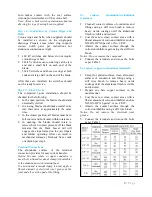
In general, operating linkages require virtually
no maintenance. However, in contaminated
atmospheres of where operation under sleet
conditions is common some lubrication at pivot
points may be desirable. The grease used should
be durable even when exposed to the elements,
and should retain its viscosity over a wide
temperature range.
COUNTERBALANCE
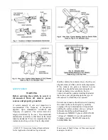
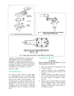
For voltage or current ratings in which blades
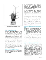
are counterbalanced, Fig. 11 shows proper
connections and the proper location of the drain
holes for the various switch mountings. The
counterbalances are assembled at the factory for
the mounting positions as required for each
installation. If it is necessary to change the
mounting position of the switch in the field, the
counterbalance must be changed, as described
below.
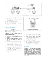
UPRIGHT TO VERTICAL
WARNING
When performing this procedure, use care
because parts are in tension.
1.
Open the switch blade to approximately the
75 degree position.
2.
Clamp the plunger of the counterbalance
with vise grip pliers against the face of the
housing.
3.
While maintaining a good hold on the blade
with your hand, carefully open the blade a
few more degrees or enough to relieve
pressure.
4.
Remove pin (A) which attaches the plunger
to the blade hinge casting. Since this pin is
larger in diameter at the center and two
shoulders hold it in place, the pin may be a
bit difficult to remove.
Summary of Contents for TTR6
Page 1: ...IB TTR6 B May 2012 ...
Page 6: ...5 P a g e ...

