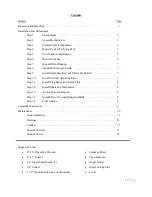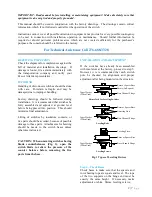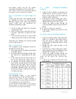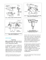
CRANKS
The two switch poles that are not connected to
the offset bearing normally use a single crank,
similar to Fig. 15. The switch pole that is
connected to the offset bearing (drive phase)
uses either a solid double crank, or a two piece
adjustable crank, as shown in Fig. 5. The offset
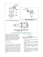
bearing used a two piece adjustable radius crank
plus a separate stop crank with multiple
mounting holes for angular adjustment. Figs. 16
and 17.
INSTRUCTIONS FOR SPECIAL SWITCHES
For switches specifically designed to operate
under abnormal ice conditions, it is important
that they be adjusted to assure the switch blade
(on a closing operation) exerts force on the jaw
stop.
FORCE VALUES
Switch Voltage
Force on Stop
8.25 thru 169 kV
80 lbs.
242 thru 840kV
40 lbs.
The blade force adjustment should be made after
the switch instillation is complete, as described
previously in this instruction manual, except for
the corona rings.
The blade force adjustment is made as follows:
Start with the three-pole switch in a position so
that the blade end contacts are at least 1 foot
from the stationary contact fingers. Using the
manual operator, and observing one switch pole,
lower the blade into the finger contact assembly
and continue to close the switch to the point
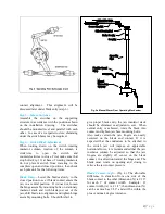
where it rests on the stop and there is
approximately 1/8” clearance between the blade
end contact and the stationary contact fingers on
each side, see Fig. 19. This is the point at which
the blade force is to be measured. It is important
that the 1/8” clearance is obtained as the switch
is being operated toward the closed position as
described and never as the switch is being
opened. This would cause an improper
adjustment.
Using a force gauge, measure the force exerted
by the blade on the jaw stop by either pushing
the blade up from below and noting the lbs. at
which the blade is lifted off the jaw stop, or by
putting a wire loop around the blade and lifting
it with the gauge and noting the lbs. required.
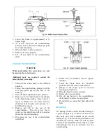
The place on the blade at which the force is
measured should be just outside the finger
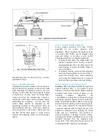
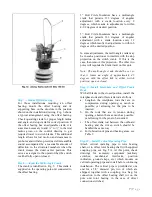
contact assembly, see Fig. 18. If the force
required is not proper, an adjustment must be
made at the hinge end of the switch. To make
the necessary adjustment, move the switch blade
to a convenient point near the full open position
and remove crank pin (B), Fig. 18, then move
and twist blade or forked link (D) to disengage
clevis (C) from crank.
If the force measured was too high, turn the
clevis (C), 1/2 turn into the forked link (D). But
if the force measured was too low, turn the
clevis (C) 1/2 turn out of the forked link and re-
connect the clevis. Check the threads on the
clevis, some switches have right hand threads
and others have left hand threads. Close the
switch to the point previously described and
again measure properly, another adjustment
must be made. Repeat the procedure previously
described. After one switch pole is satisfactorily
adjusted, the other two poles should then be
adjusted in the same manner.
Table 1
Lubrication Guide for Outdoor Switch Components
Part Name
Type Lubricants
Recommended
Amount
Applied
Qty. Req’d. for
(6) Three-pole
Switches
Jaw Fingers
NO-OX-ID Grade “A”
Special or Mobil 28
Grease
Medium
Coat
Blade Ends
NO-OX-ID Grade “A”
Special or Mobil 28
Grease
Medium
Coat
(1) Quart
Pins On current
carrying parts Mobil 28 Grease or DC-4
*
Pins On control
parts
Mobil 28 Grease or DC-4 Light Coat
(1) Quart
Bearing Areas
On control parts Mobil 28 Grease or DC-4
Medium
Coat
Terminal
Connections
NO-OX-ID Grade “A”
Special or NO 2 EJC
Heavy
Coat
(1) Quart
13 |
P a g e
Summary of Contents for TTR6
Page 1: ...IB TTR6 B May 2012 ...
Page 6: ...5 P a g e ...

