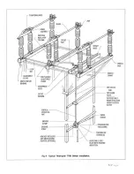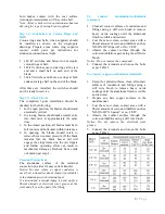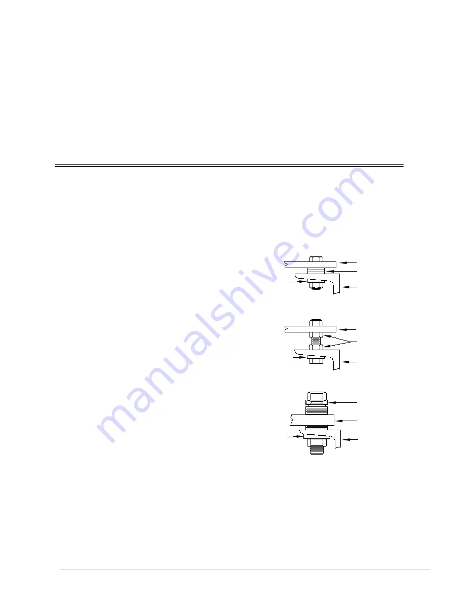
Leveling Screws
Shims Used for Leveling Switches
Shims (As Reqired)
Base Channel Flange
Rotor or Spacer Base
Leveling Screw
Rotor or Spacer Base
Base Channel Flange
Fig. 1 Types of Leveling Devices
Leveling Bolts
Rotor or Spacer Base
Base Channel Flange
Adjusting Nuts
Taper Washer
(When Used)
Taper Washer
(When Used)
Taper Washer
(When Used)
IMPORTANT: Read manual before installing or maintaining equipment! Make absolutely sure that
equipment is de-energized and properly grounded.
This manual should be used in conjunction with the factory drawings. The drawings contain critical
information, which if not followed could affect the operation of the switch.
Instructions cannot cover all possible variations in equipment nor provide for every possible contingency
to be met in connection with installation, operation or maintenance. Should further information be
required or should particular problems arise which are not covered sufficiently for the purchaser’s
purposes, the concern should be referred to the factory.
For Technical Assistance Call 276-688-3328
RECEIVING INSPECTION
Check the shipment for completeness against the
bill of material and installation drawings. If
damage is found, file a claim immediately with
the transportation company and notify your
Pascor Atlantic representative.
HANDLING
Handling of disconnect switches should be done
with care. Porcelain is fragile and may be
damaged due to improper handling.
Factory drawings should be followed during
installation. It is recommended that switches be
fully assembled and adjusted at ground level
before being placed into position. This should
minimize final adjustments.
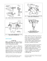
Lifting of switches by insulators, contacts, or
live parts should be avoided, because of possible
damage to these parts. Attachments for hoisting
should be made to the switch bases unless
otherwise instructed.
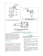
CAUTION: When uncrating switches having
blade counterbalances (Fig. 3), open the
switch blade to relieve the pressure of the
counter balance before removing the live
parts from the base.
INSTALLATION AND ADJUSTMENT
If the switches have already been assembled
with insulators at the factory, proceed to step 5.
However, it is recommended that each switch
pole be checked for alignment and proper
adjustment after being mounted on the structure.
Step 1—Check Bases
Check bases to make sure that the spacers and
rotor bearing tops are square and level. The tops
of the two supports on the hinge end must be
exactly the same height. If necessary, make
adjustments or shim. Shims, leveling screws,
2 |
P a g e
Summary of Contents for TTR6
Page 1: ...IB TTR6 B May 2012 ...
Page 6: ...5 P a g e ...

