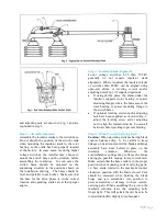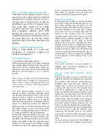
Also, Fig. 4 shows blade contact high on the
right and low on the left. The reverse is also
acceptable, high on the left and low on the right.
It is common to have both situations on one
three-pole switch. In fact, after all three poles
have been adjusted in the open position, and
then closed, you may find that one pole will be
high on the right, one fairly level and one high
on the left. This is
due to many variables and tolerances plus the
free play or clearance in pin connections of all
the switches and control parts.
Variance in contact angle is not significant
because no reduction in contact pressure occurs
until the blade exceeds ±8˚ above the horizontal.
Blade Height in Jaw
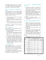
—In Fig. 3, dimension (D)
can vary from 0” to 5/8” with the switch in the
closed position. It is not usually possible to get
this dimension to be equal on all three poles of a
three-pole switch. If it’s necessary to adjust this
dimension, remove connecting pin (A) and turn
clevis (B) in or out ½ turn then reconnect and try
switch. Turning the clevis in will move the
blade away from the blade stop. Conversely,
turning the clevis out will move the blade closer
to the blade stop.
Open Blade Stop
—
On switches, there are stops
for the blade in the open position, as shown at
(C), Fig. 3. Some of these stops have flat
washers that can be relocated to raise or lower
this stop, while the voltage rated switches use
treaded bolts with lock nuts. In either case,
raising the stop surface (C) will reduce blade
opening angle; lowering the stop surface (C) will
increase the blade opening angle. After each
pole has been adjusted, set the open and closed
stop bolts of each rotating insulator.
6 |
P a g e
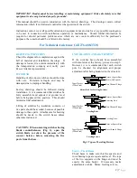
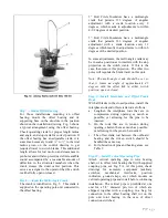
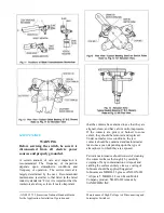
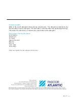
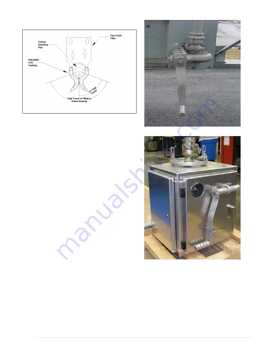
Fig. 9 MO-10 Motor Operator
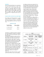
Fig. 8 Geared Mechanism
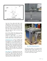
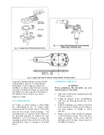
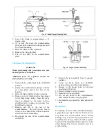
Fig 9. Operating Handle Lock Plate
Summary of Contents for TTR6
Page 1: ...IB TTR6 B May 2012 ...
Page 6: ...5 P a g e ...

