background image

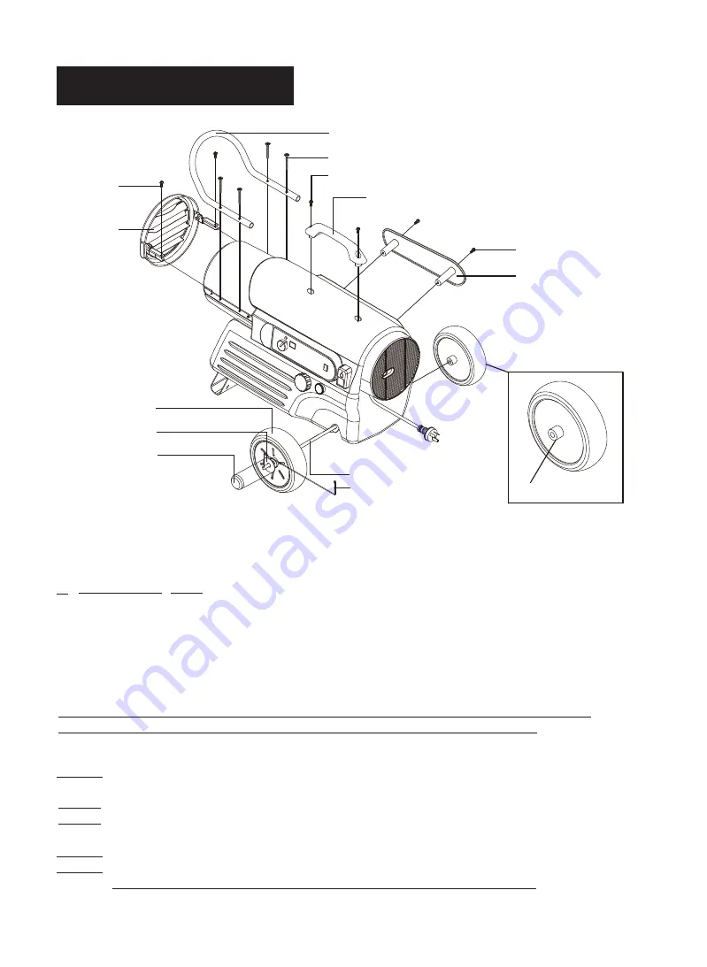
Screw(B)

Screw

Louver

Wheel Cap

Wheel Axle

Cotter Pin

Front Handle

Handle

Screw(B)

Screw(A)

Flat Washer

Wheel

Cord Wrap

7

NEVER LEAVE THE HEATER

UNATTENDED WHILE BURNING!

4. KEROSENE


(1-K)

For optimal performance of this heater, it is strongly suggested that 1-K kerosene be used. 1-K kerosene has

been refined to virtually eliminate contaminants, such as sulpher. Which can cause a rotten egg odor during

the operation of the heater. However, #1 or #2 diesel fuel


may also be used if 1-K kerosene is not


available.

Be advised that these fuels do not burn as clean as 1-K kerosene, and care should be taken to


provide more

fresh air ventilation to accomodate any added contaminants that may be added to the heated


space.

KEROSENE SHOULD ONLY BE STORED IN A  BLUE CONTAINER THAT IS CLEARLY 

MARKED “KEROSENE”.  NEVER STORE KEROSENE IN A RED CONTAINER.

Red containers are associated with 

petrol

.

NEVER store kerosene in the living space.  Kerosene should be stored in a well ventilated place outside the

living area.

NEVER


use any fuel other than 1-K


kerosene (#1 

diesel 

fuel


is an acceptable substitute.)

NEVER


use fuel such as 

petrol

, benzene, alcohol, white gas, camp stove fuel, paint thinners, or other oil

compounds in this heater.  These are volatile fuels that can cause an explosion or uncontrolled flames.

NEVER store kerosene in direct sunlight or near a source of heat.

NEVER use kerosene that has been stored from one season to the next.  Kerosene deteriorates over time.

“OLD KEROSENE” WILL NOT BURN PROPERLY IN THIS HEATER.

NOTE : Heater should be inspected before each use, and at least annually by a qualified service person.

Figure 8.  Wheel and Handle Assembly, IH125000/IH170000 Models Only

Extended Hub

Summary of Contents for IH125000

Page 1: ...SER S MANUAL has been designed to instruct you as to the proper manner in which to assemble maintain store and most importantly how to operate the heater in a safe and efficient manner Please keep this manual for future reference MODEL IH75000 IH125000 IH170000 Distributed by Companion Brands Bundoora VIC 3083 www companionbrands com au ...

Page 2: ...eater RISKOFFIREOREXPLOSION NEVER use this heater where flammable vapors may be present NEVER refill the heaters fuel tank while heater is operating or is still hot The front handle of this heater is intended to prevent direct access to heating elements and must be in place when the heater is in use The front handle does not give full protection for young children This appliance is not intended fo...

Page 3: ...h an optional thermostat or if equipped with a thermostat heater may start at any time ALWAYS locate heater on a stable and level surface ALWAYS keep children and animals away from heater Bulk fuel storage should be a minimum of 8m 25 feet from heaters torches All fuel storage should be in accordance with federal state or local authorities having jurisdiction Temperature of the floor is hot while ...

Page 4: ... E P S 3 1 9 1 IH75000 MODEL G N I W A R D S T R A P D E D O L P X E 4 1 0 2 IH75000 MODEL T S I L S T R A P 5 1 16 EXPLODED PARTS DRAWING IH125000 IH170000 MODELS 21 2 2 IH125000 IH170000 MODELS T S I L S T R A P 7 1 4 2 R E V U O L D N A E L D N A H S L E E H W T S I L S T R A P 8 1 1 INTRODUCTION Please read this USER S MANUAL carefully It will show you how to assemble maintain and operate the ...

Page 5: ...tor Lamp Handle Cord Wrap Pressure Gauge Fan Guard Fuel Tank Lower Shell Upper Shell Front Handle Hot Air Outlet Room Temp Display LED Power Reset Switch LED Power Reset Switch Thermostat Knob Fuel Gauge Fuel Cap Indicator Lamp Handle Cord Wrap Pressure Gauge Power Cord Power Cord Fan Guard Fuel Tank Louver Louver Figure 3 IH170000 MODEL Figure 2 IH125000 MODEL ...

Page 6: ...MOVE THE HEATER AND ALL PACKING MATERIALS FROM THE BOX NOTE Save the shipping carton and packing materials for future storage IH75000 IH125000 IH170000 s e Y s e Y o N l e e h W Wheel Axle No Yes Yes Wheel Cap No Yes Yes Front Handle No Yes Yes s e Y s e Y s e Y e l d n a H Cord Wrap Yes Yes Yes s e Y s e Y o N Louvre Hardware Kit HW KFA1001 Yes No No Hardware Kit HW KFA1008 No Yes Yes Wheel Axle ...

Page 7: ...points towards the wheel points towards the Wheel Support See Figure 8 page 6 2 Slide flat washer over wheel axle end past the hole in the axle Slide cotter pin into the hole in the wheel axle and using your pliers bend the legs of the Cotter Pin until it can not be removed 3 Slide wheel axle through wheel support and assemble the wheel flat washer and cotter pin as in Steps 1 and 2 4 Place wheel ...

Page 8: ...D IN A BLUE CONTAINER THAT IS CLEARLY MARKED KEROSENE NEVER STORE KEROSENE IN A RED CONTAINER Red containers are associated with petrol NEVER store kerosene in the living space Kerosene should be stored in a well ventilated place outside the living area NEVER use any fuel other than 1 K kerosene 1 diesel fuel is an acceptable substitute NEVER use fuel such as petrol benzene alcohol white gas camp ...

Page 9: ...s below the reset temperature you will be able to start your heater B Electrical System Protection The heaters electrical system is protected by a circuit breaker mounted to the power switch that protects the PCB assembly and other electrical components from damage If your heater fails to operate check this fuse first and replace as needed C Flame Out Sensor Utilizes a photocell to monitor the fla...

Page 10: ...h power switch to ON position power indicator lamp will light and heater will start NOTE Room Temp display indicates as follows When room temp is less than 5 Lo When room temp is between 0 and 45 Indicates room temperature When room temp is more than 45 Hi If heater does not start the thermostat setting may be too low turn THERMOSTAT CONTROL KNOB to higher positon to start heater If heater still d...

Page 11: ...l cause poor operation of the heater Pour the kerosene out making sure that you remove it all IMPORTANT Do not store kerosene over summer months for use during next next heating season Using old fuel could damage heater 4 Reinstall Fuel Cap See Figure 12 5 Store heater in dry well ventilated area Make sure storage place is free of dust and corrosive fumes 6 Store the heater in the original box wit...

Page 12: ...TPUT AIR INTAKE AND LINT FILTERS WASH AND DRY WITH SOAP AND WATER OR REPLACE EVERY 500 HOURS OF OPERATION OR ONCE A YEAR Remove Upper Shell See Figure 13 Remove Fan guard See Figure 14 Remove End Filter Cover Screws using medium phillips screwdriver Remove End Filter Cover Replace Air Output and Lint Filters Wash or Replace Air Intake Filter Reinstall Fan Guard and Upper Shell 11 NEVER LEAVE THE H...

Page 13: ...tor Fan Blade Motor Shaft Set Screw Flush REMOVE DIRT IN NOZZLE AS NEEDED SEE PAGE 16 Remove upper shell See page 11 Remove fan blade See page 11 Remove fuel and air line hoses from nozzle adaptor Remove ignitor wire from spark plug Remove spark plug from nozzle adaptor using medium phillips screwdriver Turn nozzle adaptor 40 turn 1 9 to counter clock wise and pull toward motor to remove See Figur...

Page 14: ...ell Install new Photocell and connect photocell connector to Circuit Board Replace Circuit Board to Side Cover R and Switch wires to Power Switch Replace Fan and Upper Shell Figure 17 Removing Spark Plug Figure 18 Replace Cleaning Photocell Ignitor Wire Screw Spark Plug Spark Plug GAP Nozzle Adaptor 2 CORRECT Switch Wires INSTALL PHOTOCELL Photocell Lens Side Cover R Circuit Board Connector Screw ...

Page 15: ...motor to reach full speed Adjust Pump Pressure Using a Flat blade screwdriver Turn Relief Valve clockwise to increase pressure Turn Relief Valve counter clockwise to decrease pressure Set Pump pressure according to the chart below Stop Heater See Operation Page 9 NOTE USE ONLY ORIGINAL EQUIPMENT REPLACEMENT PARTS USE OF ALTERNATE OR THIRD PARTY COMPONENTS WILL VOID ANY WARRANTY AND MAY CAUSE UNSAF...

Page 16: ...n Figure 21 3 Push out for arrow direction and extract side cover s bracket from rectangular hole and seperate side cover See Figure 21 4 Disconnect switch wires from power switch 5 Remove two screws using medium phillips screwdriver These screws attach circuit board to side cover see Figure 22 6 Remove fuse from fuse holder and replace fuse see Figure 22 WARNING FIRE HAZARD To avoid fire Do not s...

Page 17: ...ttached to PCB assembly between motor and MAIN 2 Bad electrical connection 1 Thermostat setting is too low spark plug PCB assembly between ignitor and MAIN 7 Bad electrical connection 6 Water in fuel tank 5 Dirt in Nozzle 4 Dirty fuel filter plug and or improper gap 3 Carbon deposits on spark 2 Wrong pump pressure 1 No fuel in tank 8 Defective Photocell PCB assembly between photocell and MAIN 7 Ba...

Page 18: ...R WHITE MOTOR PUMP EARTH GREEN BLUE BLACK RED BLUE BLACK BLACK CONTROL PCB POWER LAMP CN6 ROOM CN5 THERMOSTAT BLACK BLACK SENSOR TEMP CONTROL LED CN1 AC1 CN2 AC2 CN3 CN3 CN2 AC2 CN1 AC1 LED TEMP CONTROL SENSOR BLACK BLACK THERMOSTAT CN5 ROOM CN6 POWER LAMP CONTROL PCB BLACK BLACK BLUE RED BLACK BLUE GREEN EARTH PUMP MOTOR WHITE CAPACITOR BLACK BLACK GRAY ORANGE GRAY CN4 IGNITOR SPARK PLUG BLUE CON...

Page 19: ...p s i 240V AC 50Hz 240V AC 50Hz 240V AC 50Hz z H t l o V 9 0 9 0 6 0 s p m A 1 1 1 e s a h P Size W D H 706 427 mm 368 815 686 mm 470 937 686 mm 470 kg t h g i e W 13 SPECIFICATIONS 60 000BTU 16 5kW 105 000BTU 29kW 150 000BTU 41kW 1 7 3 4 1 19 38 45 12 26 5 28 IH125000 IH170000 IH75000 H W D H D W IH125000 IH170000 686mm 686mm 815mm 937mm 470mm 470mm 427mm 368mm 706mm ...

Page 20: ...2 10 15 33 38 15 16 7 12 6 11 31 31 1 8 10 Motor Pump Assembly 26 28 37 24 23 19 18 17 15 28 14 9 21 14 13 20 15 29 30 Burner Head Assembly 22 36 27 25 3 4 2 1 5 20 1 20 2 20 4 20 5 20 6 20 7 20 8 20 3 22 17 22 4 22 12 22 13 22 11 22 7 22 16 22 14 22 10 22 6 22 5 22 5 22 1 22 3 22 8 22 9 22 18 22 19 22 20 22 15 13 ...

Page 21: ...16 00 2154 0083 00 3970 0216 00 3820 0261 00 3121 0481 00 Pump Body Bolt BH Special Insert Rotor Blade End Pump Cover Elbow Flange Bolt Lint Filter Output Filter Intake Filter End Filter Cover Ball Spring Adjusting Screw Flange Bolt Fan Assembly Set Screw Pressure Gauge Fan Guard Ignitor Screw TH2S Shell Upper Assembly Shell Cover Main P C B Assembly Fuse Thermostat Control Knob Side Cover R Brack...

Page 22: ...15 33 15 32 31 2 31 16 10 28 37 31 1 28 24 23 22 15 21 20 19 18 17 15 14 13 13 12 11 9 8 7 6 10 14 36 27 26 25 20 6 20 4 Motor Pump Assembly 15 30 29 20 8 20 7 20 5 20 3 20 2 Burner Head Assembly 22 4 22 5 22 12 22 14 22 13 22 21 22 20 22 8 22 16 22 19 22 17 22 18 22 6 22 2 22 3 22 7 22 11 22 15 22 10 22 9 22 1 5 4 1 3 2 ...

Page 23: ...52 0122 00 3531 0025 00 2152 0005 00 4343 0016 00 3431 0010 00 3311 0002 00 3651 0012 00 4329 0079 00 3341 0017 00 2154 0084 00 3970 0217 00 3820 0218 00 3121 0482 00 4331 0022 00 3541 0022 00 4321 0198 00 3231 0052 00 3451 0008 00 2151 0011 00 2156 0022 00 3231 0123 00 3231 0122 00 2155 0010 00 2151 0044 01 3231 0120 00 3231 0121 00 3713 0022 00 3131 0182 00 3712 0013 00 3980 0267 00 3341 0002 00...

Page 24: ...4 0004 00 4323 0004 00 3740 0049 00 3221 0032 00 39E0 0028 00 4312 0044 00 3111 0220 02 2151 0020 02 3211 0020 00 215A 0050 00 3920 0025 00 3231 0146 00 3211 0022 00 3131 0351 00 3221 0059 16 39A0 0153 00 3211 0024 00 3131 0352 00 3231 0181 00 4329 0016 00 3631 0005 00 2155 0004 00 3631 0005 00 3221 0029 00 3541 0023 00 3431 0016 00 3231 0053 00 4329 0016 00 2154 0007 00 4323 0004 00 3740 0049 00 ...

Page 25: ...nt 3551 0039 02 3551 0040 02 1 2 Handle 3231 0126 00 3231 0126 00 1 3 Cord Wrap 3221 0057 00 3221 0057 00 1 4 Wheel Axle 3541 0064 00 3541 0064 00 1 5 Wheel 2156 0026 00 2156 0026 00 2 6 Wheel Cap 3231 0100 00 3231 0100 00 2 7 Hardware Kit HW KFA1008 HW KFA1008 1 4 A w e r c S 1 7 4 B w e r c S 2 7 2 r e h s a W t a l F 3 7 2 n i P r e t t o C 4 7 8 Louvre 2156 0036 00 2156 0036 00 1 KEY NO DESCRI...

Reviews: