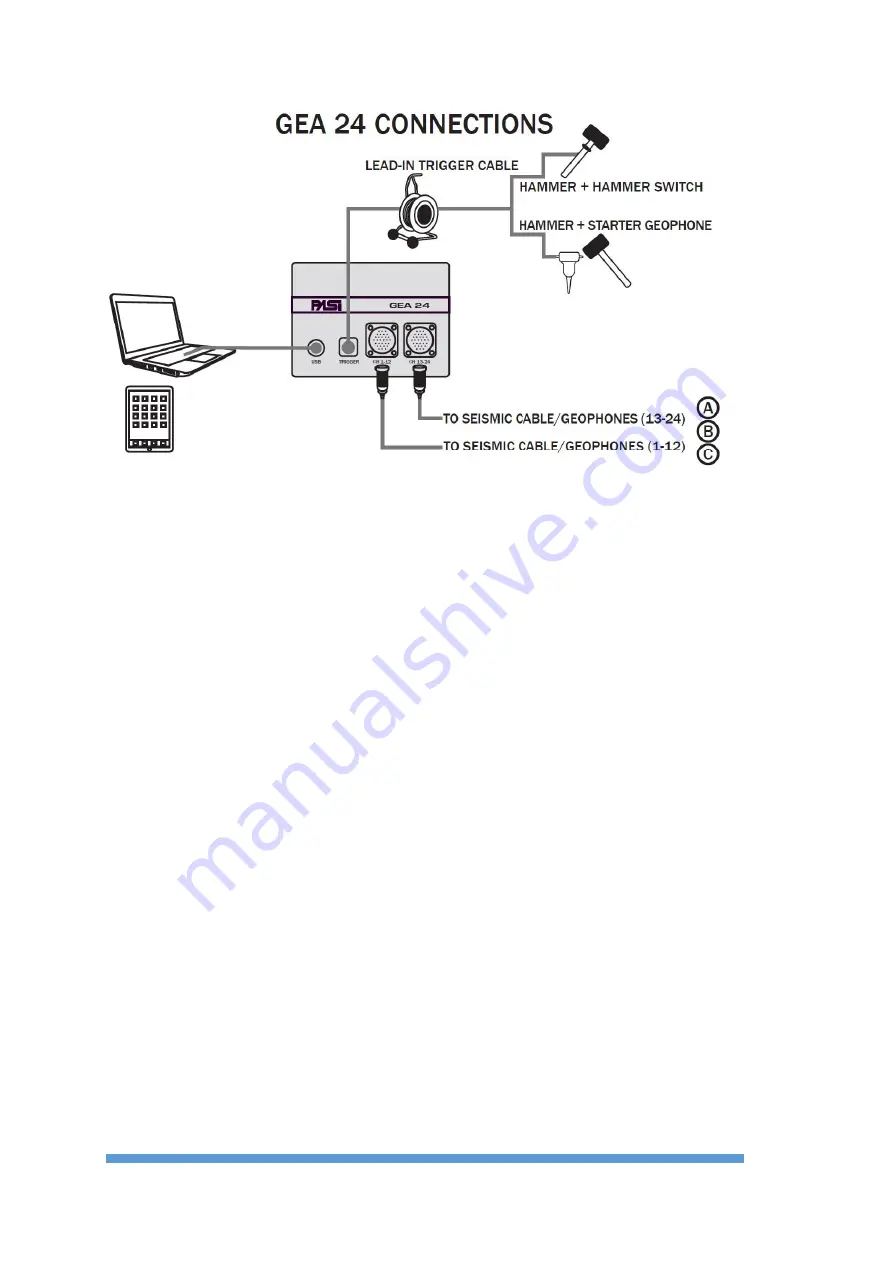
14
F
IGURE
2
G
EA
24
CONNECTION SCHEME
In addition to the seismic cables, to become "active" GEA24 must be connected to a
trigger or starter geophone using the supplied special connector.
Power supply
As indicated in Par.1.2, Gea24 is powered by the PC via the USB port; an external 12V
battery is not necessary.
Summary of Contents for GEA24
Page 2: ......
Page 5: ...GEA24 SEISMOGRAPH 5 Table of Contents ...
Page 7: ...GEA24 SEISMOGRAPH 7 Important Notice ...
Page 9: ...GEA24 SEISMOGRAPH 9 Warranty and safety instructions ...
Page 11: ...GEA24 SEISMOGRAPH 11 Introduction ...
Page 54: ...54 Appendix A Technical Specifications ...
Page 55: ...GEA24 SEISMOGRAPH 55 Appendix B Appendix B How to place the piezoelectric shock sensor ...
Page 56: ...56 Appendix C Trigger connector FIGURE 17 TRIGGER CONNECTOR ...
Page 58: ...58 48 Channel seismograph 24 Channels cables ...
Page 59: ...GEA24 SEISMOGRAPH 59 Appendix D Line Connections ...


