GEA24 SEISMOGRAPH
29
Full description of graphical interface and functionality
6.3.3
Geophone configuration Window
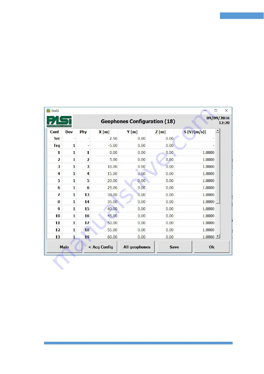
The geophone Configuration window allows you to display all the configuration
parameters of all the geophones in a table, to this you add the configuration concerning
the source (position of the energization point) and the trigger (geophone starter,
piezoelectric starter, etc.). The table shows the values that refer to the parameters stored
in the selected template by entering the procedure storage, and any changes made by the
operator.
Figure 8 shows an example of the window
F
IGURE
8
-
C
ONFIGURATION
V
IEW WINDOW
-
ALL GEOPHONES
The example shown in figure 8 is a configuration of the lines realized by enabling the
physical geophones from 1 to 6 on the left side of the first system, the physical
geophones from 13 to 24 on the right side of the first system, disabling all of the
geophones of the second system and not reversing the order on the lines.
With this configuration there are 18 geophones in the table, since only the enabled
geophones for collecting measurements are reported.
The table has the following columns.
Summary of Contents for GEA24
Page 2: ......
Page 5: ...GEA24 SEISMOGRAPH 5 Table of Contents ...
Page 7: ...GEA24 SEISMOGRAPH 7 Important Notice ...
Page 9: ...GEA24 SEISMOGRAPH 9 Warranty and safety instructions ...
Page 11: ...GEA24 SEISMOGRAPH 11 Introduction ...
Page 54: ...54 Appendix A Technical Specifications ...
Page 55: ...GEA24 SEISMOGRAPH 55 Appendix B Appendix B How to place the piezoelectric shock sensor ...
Page 56: ...56 Appendix C Trigger connector FIGURE 17 TRIGGER CONNECTOR ...
Page 58: ...58 48 Channel seismograph 24 Channels cables ...
Page 59: ...GEA24 SEISMOGRAPH 59 Appendix D Line Connections ...


