13
8
I
GB
20
– Installare l'astina di livello (6) nella scatola,
accertandosi che sia correttamente inserita.
– Avviare il motore ed azionare per alcuni
cicli il sollevatore idraulico, quindi lasciarlo in
posizione completamente abbassata.
– Ricontrollare il livello e, se necessario, rab-
boccare fino al livello massimo.
• Frizione
La frizione, essendo idraulica, non richiede
normalmente una registrazione; è bene
comunque verificare che, con il pedale rila-
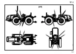
sciato, la testa del pistoncino (1, fig. 2
0
) del
regolatore di pressione (2) risulti a fine corsa
verso l'alto. In caso contrario la pressione di
comando della frizione è insufficiente a
quanto stabilito, con possibilità di slitta-
mento. Per la regolazione, allentare il contro-
dado (3) e regolare la forcella (4) (vedere
dett. A).
Se la frizione trascina, controllare che, con il
pedale premuto a fondo, la testa del piston-
cino (1) sia staccato dal comando; in caso
contrario, regolare la vite di registro (4)
(vedere dett. A).
Ver. Reversibili
- Una volta effettuata la regi-
strazione sopra descritta, ripetere la stessa
procedura con il secondo pedale frizione la
cui registrazione deve essere effettuata attra-
verso i dadi di registro (5) e (6).
– Recheck the level and top up to the max.
level if necessary.
• Clutch
Since the clutch is hydraulic, is normally
does not have to be registered.
However, it is good operating practice to
check that when the pedal is released, the
head of the pressure regulating (2) piston (1,
fig. 2
0
) is the full travel position at the top. If
not, the clutch control pressure is insufficient
and the clutch can slip. T
o adjust, loosen the locking nut (3) and regu-
late with the fork (4) (refer to det. A).
If the clutch draws, check if, when the pedal
is depressed all the way down, the head of
the piston (1) is detached from the control.
If it is not, regulate the adjustment screw (4).
(Refer to det. A).
Ver. Reversible
- After you do the adjust-
ment described above, repeat the same pro-
cedure on the second clutch pedal. In this
case, the adjustment is performed by use of
the adjustment nuts (5) (6), (detail b), located
under the right footboard.
Summary of Contents for Mars 7.75 EP
Page 2: ......
Page 40: ...38 I GB 3 3 ...
Page 41: ...39 I GB 4 4 ...
Page 42: ...40 I GB 5 ...
Page 43: ...41 I GB 6 ...
Page 45: ...43 I GB 7 2 ...
Page 96: ...94 I GB 11 11 1 ...
Page 97: ...95 I GB 11 2 ...
Page 118: ...116 I GB 15 15 1 ...
Page 119: ...117 I GB 16 2 ...
Page 120: ...118 I GB 16 3 ...
Page 121: ...119 I GB 16 4 ...
Page 130: ...128 I GB 17 17 1 ...
Page 131: ...129 I GB 17 2 ...
Page 153: ......


