Angle Sensor
© PAT
Rev. - 12/18/00 // CSH.
190118_-.DOC
17
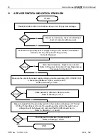
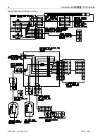
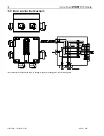
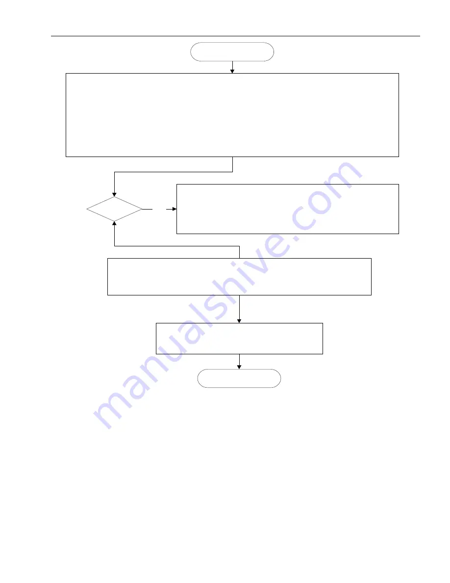
Follow signal flow from angle sensor to central unit. Refer to drawing 1 or 2.
Measure sensor input voltage between wires X1:28 as Ground, X1:29 has to be between 1.1V or
4mA (=90º) and 5.5V or 20mA (=0º)
Refer to Angle Sensor, Theory 1, for information on the difference between voltage and
amperage measurements.
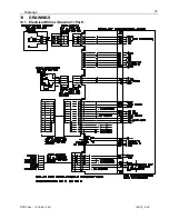
Three-conductor wires are:
X1:26 = A = +Ub
X1:29 = B = signal (4 ... 20mA)
X1:28 = C = GND
PREVIOUS PAGE
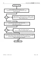
Replace angle sensor.
Refer to Adjustment Procedure 3.
Somewhere between angle sensor and central unit the signal is lost.
Check wiring and replace.
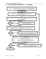
Check analog input board: voltage between X1:4 on analog
input board and MP0 (GND). 0.5V to 4.5V is correct. If
otherwise, main or analog board defective. Replace main board
and/or analog board.
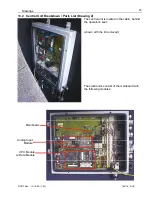
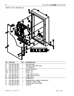
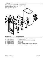
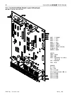
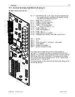
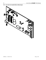
Refer to Drawings 2, 4 and 5, Main board or Analog Input
Module.
Correct?
YES
END


