TROUBLESHOOTING FLOW CHARTS
© PAT
Rev. B 03/08/02 // CLC
031-300 / 190007_b.DOC
5
4.2
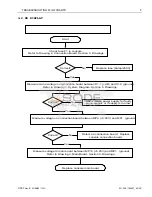
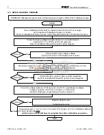
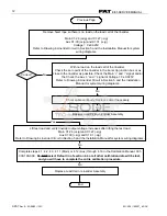
NO DISPLAY
Measure crane voltage on connection board between X1:1 (+UB) and X1:3 (ground).
Refer to Drawing 1, System Diagram, Section 5. Drawings.
Check fuse F1 in console.
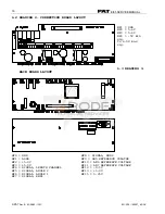
Refer to Drawing 2, Connection Board, Section 5. Drawings.
Correct?
Replace fuse (2amp/250V)
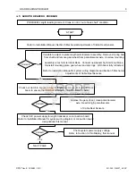
Measure voltage on connection board between MP4 (+5.25V) and MP1 (ground).
Correct?
Defect on connection board. Replace
console connection board.
Replace console main board.
Correct?
Start
No
Check crane power supply for faulty
crane electric or if supply is too low.
No
No
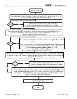
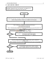
Measure voltage to main board between MP15 (+5.25V) and MP1 (ground).
Refer to Drawing 3, Main Board, Section 5. Drawings..
Yes
Yes
Yes


