SYSTEM DRAWINGS
© PAT
Rev. B 03/08/02 // CLC
031-300 / 190007_b.DOC
15
6
SYSTEM DRAWINGS
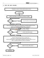
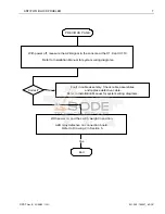
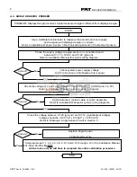
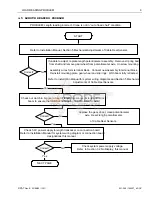
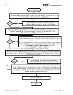
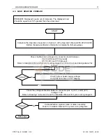
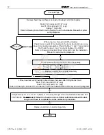
The PAT EI65 System drawings in this section are provided as reference
material for the troubleshooting flow charts. Use the drawings in
conjunction with the flow charts to help understand the operation of the
EI65 system.
Drawing List:
1.
System Diagram
2.
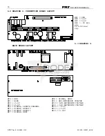
Connection Board Layout
3.
Main Board Layout
4.
Anti-Two Block Circuit
5.
Angle Sensor Adjustment
6.
Angle Sensor Circuit
7.
Linerider Circuit
Refer to the Operator’s Manual for basic component layout on the crane and
console drawing. The EI65 console connection board has the following
terminal designations.
Connection Board 056-065-300-002 Designations:
1
+ Battery
17
+5VDC
2
+ Battery
18
Main Boom angle input
3
- Battery
19
Main Boom Length
input
4
- Battery
20
Analog Ground
5
Load Limit output
21
+5VDC
6
A2B Relay output 2
22
Jib Angle input
7
A2B Relay output 1
23
Analog Ground
8
Peripheral ground
24
Analog Ground
9
A2B 1 input
25
+9VDC
10
A2B Ground
26
KMD1 +Signal input
11
A2B 2 input
27
KMD1 -Signal input
12
A2B Ground
28
-9VDC
13
3rd Wrap Switch input
29
+9VDC
14
3rd Wrap Switch
ground
30
KMD2 +Signal input
15
Digital input 1
31
KMD2 -Signal input
16
Digital input 2
32
-9VDC
6.1
DRAWING 1. SYSTEM WIRING DIAGRAM (REFER TO INSTALLLATION MANUAL
031-300-190-008)

