MODEL 7748 SINGLE CHANNEL RS530 DB25 A/B SWITCH W/CUTOFF, TELNET AND GUI
Electro Standards Laboratories, Inc.
(401) 943-1164
www.electrostandards.com - pg 8 - Pub. 4703-02
OPERATION
The Model 7748 can be operated either by the front panel or through its
Remote port.
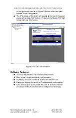
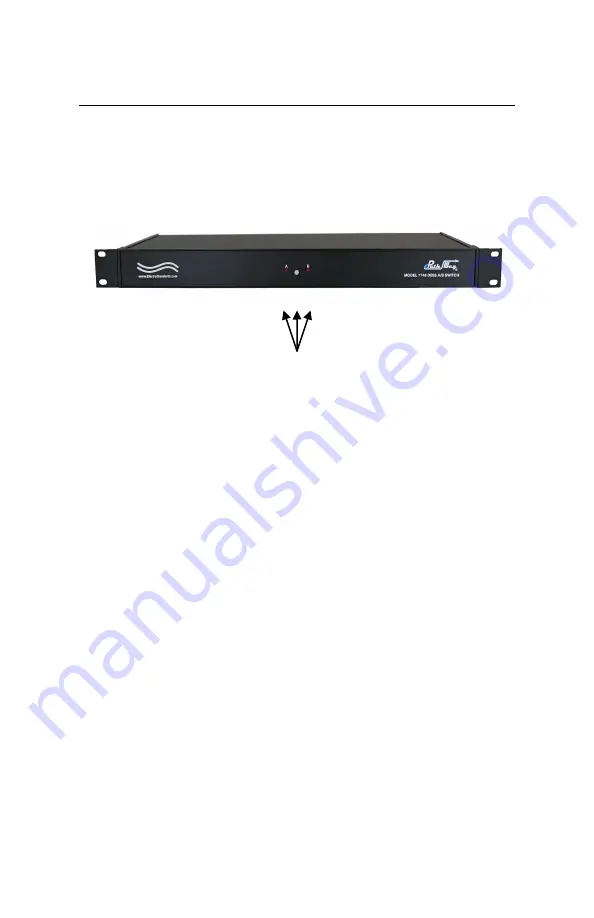
Figure 2: Model 7748 Front Panel
Manual Control
The front panel view of the Switch System is shown in the above figure.
On the front of the switch are the following controls and indicators:
•
A, B INDICATORS
– Red LED’s indicate the switch position as
well as the power status.
o
The LED in the steady state indicates the position of
the switch.
o
If the front panel pushbutton is locked and the button
is pressed, both LED’s will light until the pushbutton is
released.
o
When first powering up, both LED’s will light and flash
during the power up routine.
o
If the Remote Ethernet port is reset on power up, both
LED’s will light and flash a few times for several
seconds until completing its routine and displaying the
present position.
•
MANUAL PUSHBUTTON
– The front panel pushbutton allows
the switch position to be changed.
o
Depressing and releasing the pushbutton allows the
user to toggle the switch position.
o
Pushbutton control can be inhibited if locked out
remotely.
o
Pressing and holding the pushbutton on power up will
initiate the Remote Ethernet port reset routine.
Model 7748 Front Panel
Pushbutton and LED’s


