background image

– 38 –

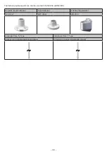
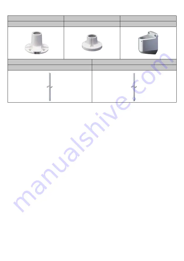
The following optional parts can also be used with the NE-24A and NE-M1A.

Round Multi-pitch Bracket

Round Bracket

Wall Mounting Bracket

SZP-001W

SZP-003W

SZK-001U

Aluminum Pole   N Type

Aluminum Pole   T Type

POLE22-[0100/0300/0500/0800/1000]AN

POLE22-[0100/0300/0500/0800/1000]AT

Summary of Contents for NE-24A Series

Page 1: ...on at the end of this document and contact your nearest PATLITE Sales Representative To the Contractor Read this manual carefully prior to installation Be sure to return this manual to the customer Signal Beacon TYPE NE 24A NE M1A Signal Beacon TYPE NE IL Complete Operation Manual Installation Operation Maintenance GA0001118_01 Page 1 Read this First 2 2 Model Number Configuration 3 3 Names and Di...

Page 2: ...and or falling off the machinery Caution Be sure to put a fuse in the wiring circuit between the power source and equipment for protection If a fuse is not added it may result in product and or equipment failure Be sure to prevent electrostatic damage due to discharge when working with this product for wiring exchanging units setting up parameters etc by discharging static electricity on your body...

Page 3: ... 3 2 Model Number Configuration TYPE NE 24A Model Rated Voltage LED Unit Color Assembly Model NE A 24 24 V DC R Red Y Amber G Green B Blue C White Model Number Example NE 24A R 24 V DC Red ...

Page 4: ... Voltage Touch Sensor Buzzer LED Unit Color Assembly Model NE A M Multicolor M1 12 24 V DC B With Buzzer N No Buzzer T With Touch Sensor N No Touch Sensor Model Number Example NE M1ATB M 12 24 V DC Touch Sensor Buzzer Multicolor ...

Page 5: ...lor Assembly Model NE IL M Multicolor X With Touch Sensor General Purpose Digital Analog Input T With Touch Sensor N No Touch Sensor B With Buzzer Model Number Example NE ILXB M IO Link Touch Sensor General Purpose Digital Analog Input Buzzer Multicolor ...

Page 6: ... Globe Case Nameplate O Ring Waterproof Sheet Accessory Waterproof Sheet Mounting Holes 1 Ø 4 5 Wire Exit Hole Ø 13 3 Bottom View Without waterproof sheet 1 The mounting holes 2 positions are designed to be punched out Drill the Ø 4 5 mounting holes from the top ...

Page 7: ... M1ATB M Buzzer Case Aperture Section Waterproof Sheet Cable Gland Cable UL2464 AWG24 7 Color Red Green Blue Yellow Purple Pink Gray Cable length 2090 Cable diameter Max 6 5 Material PVC Globe O Ring Nameplate Accessory Waterproof Sheet Ø 2 1 1 Mounting Holes 1 Ø 4 5 Touch Sensor Rear View Without Cable Gland 1 The mounting holes 2 positions are designed to be punched out Drill the Ø 4 5 mounting ...

Page 8: ...ILXB M and NE ILTB M Buzzer Case Aperture Section Waterproof Sheet M30 Nut M30 1 5 M12 Connector Globe O Ring Nameplate L L L L IO Link C Q M12 Connector Pin Configuration NE ILXB M M12 Connector Pin Configuration NE ILTB M NE ILNB M IO Link C Q Analog GND N C N C N C Analog IN Digital GND Digital IN ...

Page 9: ...turdy surface Install the signal beacon on a level surface When waterproofing apply a sealing coating onto the nuts on the backside of the installation surface Provide a sealant coating around the wire exit hole or use a Cable Gland TYPE NE 24A 1 5 2 3 4 Installation Example Positioning Mark Locked Unlocked 1 Unlock the globe by holding and rotating it in a counter clockwise direction then lift it...

Page 10: ...ve paper from the waterproof sheet and apply it to the case 4 Affix the product to the installation surface with screws and nuts Installation screws and nuts are not included with this product 5 Set the globe with aligning the positioning mark after attaching the case then turn the globe clockwise to lock it Installation Dimension Unit mm 35 5 Wire Exit Hole Installation Holes Ø 16 When the Cable ...

Page 11: ...allation Example Waterproof Sheet 1 Remove the M30 nut 2 Fix on the mounting surface with the M30 nut 3 Connect the M12 cable to the M12 Connector Installation Dimension Unit mm Installation Holes Ø 31 Tightening torque 4 5 N m ...

Page 12: ...se direction 2 Connect the wires to the screwless terminal block 3 Attach the globe by screwing it in a clockwise direction The terminals have no polarity Screwless Terminal Block wiring method 1 A minus driver etc is used to pry the lever slot of the Terminal Block open by pushing straight onto the lever slot Lever 2 The stripped side of the lead wire is inserted in the slot 3 The driver is remov...

Page 13: ...Drive NPN Transistor Fuse 1A I O Unit Power Supply DC 24 V C I O Unit Drive PNP Transistor Fuse 1 A I O Unit Power Supply DC 24 V Fuse Fuse Rating 250 V 1 A External Contact Capacity Current Capacity Is 50 mA Voltage Capacity Vs 35 V Transistor NPN or PNP Current Capacity Ic 50 mA Withstand Voltage Vc 35 V Leakage Current IL 0 1 mA No significant inrush current present ...

Page 14: ...0 V or less Load Current 100 mmA or less Fuse 1 A External Contact Power Supply Do not connect directly to the power supply This will cause damage Load GND LED Color Red Green Blue Yellow Cyan Purple White Wiring Red Green Blue Red Green Blue Green Red Blue Red Green Blue NOTE No need to connect the buzzer purple wire for NE M1ANN M When the blink control is not necessary for NE M1ANN M NE M1ANB M...

Page 15: ...ital GND Pin 3 L Pin 5 IO Link C Q Pin 8 L Pin 7 Digital Input NE ILTB M NE ILNB M C Q L L IO Link Master L Pin 1 IO Link C Q Pin 4 L Pin 3 External Contact Capacity Current Capacity Is 50 mA Voltage Capacity Vs 35 V Leakage Current IL 0 1 mA Analog Input Input Range 4 mA 20 mA Update interval 20 ms Digital Input Driving Method NPN open drain Update interval 20 ms ...

Page 16: ...ons the touch sensor input switching can be set Caution Do not use excess force when performing operations Failure to comply will result in damage due to breakage or deformation Do not use sharp pointed objects to perform operations Failure to comply may result in damage and inoperative switches or hinder contact between contact parts OFF ON Top view of product with globe removed ...

Page 17: ...attern Settings Change Touch Sensor Input Settings Change Touch Sensor Input LED Color Settings NE M1ANB Switch 1 Switch 2 Switch 3 Switch 4 Function Buzzer Pattern Settings Not used Not used Not used Buzzer Pattern Settings Change the buzzer pattern as shown in the following table Switch Position OFF ON Buzzer Pattern Rapid intermittent beep call sign Continuous beep sound Change Touch Sensor Inp...

Page 18: ...e The LED will remain off until touching the light again even if the condition of the signal wire has been changed Notice Always move your hand away from the touch sensor after changing the DIP Switch About the Touch Sensor To turn the touch sensor to ON touch the following symbol on the top of the globe with the middle of your finger or palm of your hand The response time of the touch sensor is 1...

Page 19: ...ification Mode Level Mode Analog Input Mode NE ILXB only Digital Input Mode NE ILXB only The parameters used in each mode are shown in the following table Refer to Common Items for Each Mode P 23 for common items Mode Parameter Color Specification Level Analog Input Digital Input 2000 LED Intensity 2001 Buzzer Sound Level 2002 SIO LED Color 2003 SIO LED Pattern 2004 Touch Sensor LED Color 2005 Tou...

Page 20: ...0 mA 21 mA 500 531 Color Specification Mode In this mode LED and buzzer details are specified for control Other settings are specified using the parameters Send the processed data by referring to the table below bit7 bit6 bit5 bit4 bit3 bit2 bit1 bit0 Byte 0 LED Pattern Not used LED Color Byte 1 Buzzer Pattern Not used Buzzer ON OFF Level Mode In this mode LED and buzzer details are set using the ...

Page 21: ...zer control uses analog input values without using processed data Settings are specified using the parameters Refer to the following image for values used for analog input Current value 21mA 20mA 4mA 3 2mA 0 25 500 531 Analog Input Value Resolution ...

Page 22: ...Color LED Pattern Buzzer Pattern 49 OFF Lit Buzzer 0 OFF 50 99 Blue 1 sec Flash Slow Buzzer 0 OFF 100 149 Blue 500 ms Flash Medium Buzzer 0 OFF 150 199 Blue Lit Buzzer 0 OFF 200 249 Green 1 sec Flash Slow Buzzer 0 OFF 250 299 Green 500 ms Flash Medium Buzzer 0 OFF 300 349 Green Lit Buzzer 0 OFF 350 399 Yellow 1 sec Flash Slow Buzzer 0 OFF 400 449 Yellow 500 ms Flash Medium Buzzer 0 OFF 450 474 Yel...

Page 23: ...llow 3 Blue 4 Purple 5 Cyan 6 White 7 About LED Patterns The LED Pattern used in each mode is shown in the following table Pattern Setting Name Interval Lit 0 1 sec Flash Slow 500 ms 1 500 ms Flash Medium 250 ms 2 250 ms Flash Fast 125 ms 3 Single Flash 500 ms 4 Double Flash 500 ms 5 Triple Flash 500 ms 6 Sine Curve slow 6 s 7 Sine Curve fast 3 s 8 ...

Page 24: ...ontinuous beep sound 1 Rapid intermittent beep call sign 2 Rapid hi low 3 Sweep sound 4 Continuous beep sound 500ms ON 500ms OFF 5 Rapid intermittent beep call sign 500ms ON 500ms OFF 6 Rapid hi low 500ms ON 500ms OFF 7 Sweep sound 500ms ON 500ms OFF 8 About the Touch Sensor Refer to About the Touch Sensor P 18 for the NE M1A ...

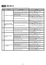
Page 25: ...elow No Problem Confirmation Remedy 1 The LED does not light Has the wiring been connected properly Wire the LED again while referring to the instructions in 5 Wiring P 12 Is the power source supplying the proper voltage and current Use the appropriate voltage Has the fuse blown Replace the fuse if it has blown ...

Page 26: ... touch sensor input and signal wire input 3 The LED does not flash Has the wiring been connected properly Wire the LED again while referring to the instructions in 5 Wiring P 12 Check the product model Products with T in the model name do not have a flash function 4 The buzzer does not sound Has the wiring been connected properly Wire the LED again while referring to the instructions in 5 Wiring P...

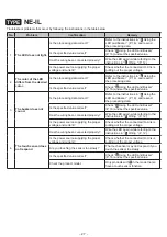
Page 27: ...ecified value 3 The buzzer does not sound Is the processing data correct Refer to the instructions in 6 Using the LED and Buzzer P 16 and resend the processing data Is the specified value correct Check 6 Using the LED and Buzzer P 16 and set the specified value Has the wiring been connected properly Wire the LED again while referring to the instructions in 5 Wiring P 12 Is the power source supplyi...

Page 28: ...conditions When installed in all directions Vibration Resistance 5 MΩ or more at 500 V DC between charging parts and non charging metal parts Withstanding voltage 1 minute at 500 V AC between charging parts and non charging metal parts Luminous colors Red Yellow Green Blue White Mass Tolerance 10 0 06 kg Compliance standards EMC Directive EN 61000 6 4 EN 61000 6 2 RoHS Directive EN 50581 UL 508 CS...

Page 29: ...nditions When installed in the upright direction Vibration Resistance 5 MΩ or more at 500 V DC between charging parts and non charging metal parts Withstanding voltage 1 minute at 500 V AC between charging parts and non charging metal parts Sound pressure level Typ 88 dB Environmental conditions At 1 m in front from the center buzzer pattern 2 Continuous beep sound Touch Sensing Input Method Elect...

Page 30: ... metal parts Withstanding voltage 1 minute at 500 V AC between charging parts and non charging metal parts Sound pressure level Typ 88 dB Environmental conditions At 1 m in front from the center buzzer pattern 1 Continuous beep sound Touch Sensing Input Method Electrostatic Capacitance Analog input range 4 mA to 20 mA Digital Input Voltage contact NPN PNP Transistor Mass Tolerance 10 0 10 kg Exter...

Page 31: ... 31 9 Service Parts These are the various parts for the customer to use when repairing or replacing parts for the product O Ring Number 1 ...

Page 32: ...del Body Color Model Number NE 001 D D Off darkgray External Diagram Unit mm Applicable pole Applicable bracket 47 POLE 800A21 POLE 300A21 POLE 100A21 SZ 010 SZ 016A General Specifications Product Name Pole Bracket Model NE 001D Installation location Indoor Installation direction Upright direction Mass Tolerance 10 0 031 kg With one sealing rubber attached ...

Page 33: ... pole TYPE NE IL TYPE NE 24A NE M1A Caution After mounting the pole check that the pole does not come loose Use in an area with no vibrations Remove the M30 nut on the main unit Recommended installation screw 4 12 mm Self tapping screw for plastics Recommended torque 1 N m ...

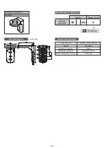
Page 34: ...uration Model Body Color Model Number NE 002 D D Off darkgray External Diagram Unit mm General Specifications Product Name Wall Mounting Bracket Model NE 002D Installation location Indoor Installation direction Upright direction Mass Tolerance 10 0 034 kg ...

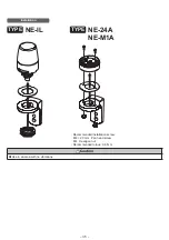
Page 35: ... 35 Installation TYPE NE IL TYPE NE 24A NE M1A Caution Use in an area with no vibrations Recommended installation screw M4 20 mm Pan head screw M4 Hexagon nut Recommended torque 0 6 N m ...

Page 36: ...del v Configuration Model Body Color Model Number SZP 092 D D Off darkgray External Diagram Unit mm General Specifications Product Name NPT Pole Bracket Model SZP 092D Installation location Indoor Installation direction Upright direction Mass Tolerance 10 0 023 kg ...

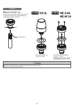
Page 37: ...mage Tightening torque 2 25 N m A A 1 2 NPT pole TYPE NE IL TYPE NE 24A NE M1A Caution After mounting the pole check that the pole does not come loose Use in an area with no vibrations Remove the M30 nut on the main unit Recommended installation screw 4 12 mm Self tapping Screw for plastics Recommended torque 1 N m ...

Page 38: ...lso be used with the NE 24A and NE M1A Round Multi pitch Bracket Round Bracket Wall Mounting Bracket SZP 001W SZP 003W SZK 001U Aluminum Pole N Type Aluminum Pole T Type POLE22 0100 0300 0500 0800 1000 AN POLE22 0100 0300 0500 0800 1000 AT ...

Reviews: