background image

22 | P a g e


PATON

®

 PSI PRO 270 / 350  400 V DC MIG/MAG TIG/MMA


4.7. LINEAR DECREASE OF WELDING CURRENT  

This function is designed for smooth welding of a welding crater, which can be formed in the welding 
pool due to electromagnetic blow forces generated by the welding arc. The crater so formed can be a 
source  of  future  welding  defects.  By  default,  the  period 

[TIME  DOWN  ARC]


of  linear  decrease  of 

welding current is 3.0 s and can be varied by the operator at his option. 


The procedure for changing the values of the operational parameters of the welding unit is described in 

Section 6.1. 


4.8. WELDING CRATER CURRENT  

This  function  is  designed  for  decreasing  the  welding  current  at  the  end  of  welding.  The  decrease  of 
welding current is required for welding a crater at the end of the weld. To activate the function for the 
TIG-4T  welding  process,  press  and  hold  the  button  of  the  welding  torch  for  the  second  time.  By 
default, the 

[POST CRATER ARC]

 crater welding current is 20 A. 


The procedure for changing the values of the operational parameters of the welding unit is described in 

Section 6.1. 


4.9. WELDING AT PULSE WELDING CURRENT  

This  function  is  designed  to  simplify  the  control  of  a  welding  process  in  various  spatial  welding 
positions, excluding a flat welding position. This function is also used in  welding nonferrous metals. 
When  this  function  is  activated,  the  application  of  pulse  welding  current  improves  the  mixing  of 
molten metals in the weld area and causes forced action on the transfer of molten metal drops into the 
welding pool, therefore the stability of the weld formation and the stability of the welding process are 
improved. The  pulse  welding  current  in  the  manual  arc  welding  process  affects  the  weld  parameters 
similar to  the movement  of the operator hand in manual  arc welding process, specifically at  hard-to-
reach places.  
The proper adjustment of the welding process parameters in the welding at pulse welding current has a 
direct effect on the weld quality, specifically reduces weld metal porosity and decreases the graininess 
of the weld metal. As a result of the improved weld quality, the weld strength increases. 
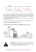
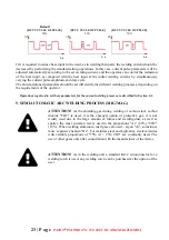
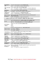
To  activate  this  function,  it  is  necessary  to  set  the  following  three  operational  parameters  of  the 
welding process:  current  pulse amplitude 

[POWER  OF  PULSE]

, current  pulse frequency 

[FREQUENCY 

OF  PULSE]

,  and  duty  cycle 

[FREQUENCY  OF  PULSE]

.  By  default,  the  current  pulse  amplitude  is  0 

[OFF], 

that is, the function is switched off, the current pulse frequency is 10.0 Hz, and the duty cycle 

is  50%.  To  activate  the  function,  set  the  current  pulse  amplitude 

[POWER  OF  PULSE]

  higher  than  0. 

The  current  pulse  amplitude  should  be  set  in  percentage  of  the  welding  current  specified  for  the 
welding process. 

Example

Welding is to be performed with welding nonconsumable tungsten electrode 

Ф

2.0 mm 

in  diameter.  The  set  welding  current  is  100  A.  The  current  pulse 

[POWER  OF  PULSE]


amplitude  is  30%.  The  current  pulse  frequency 

[FREQUENCY  OF  PULSE]

  is  10.0  Hz 

(default value). The duty cycle 

[DUTY CYCLE OF PULSE]

 is 50% (default value). 

Result:


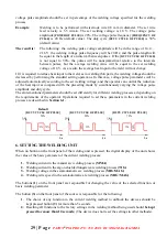
The result is the following: the welding current pulse amplitude will be in the range of  
70 … 130 A, the current pulse frequency will be 10.0 Hz, and the current pulse length 
will be equal to the length of an interval between pulses. If the duty cycle is not equal to 
50%, the current pulses will be nonsymmetrical relative to the intervals between pulses, 
but the average welding current value will be equal to the set welding current value of 
100 A. As a result, the average heat input to the weld will not change. 


Summary of Contents for PSI 270 PRO 400 V

Page 1: ...0 P a g e PATON PSI PRO 270 350 400 V DC MIG MAG TIG MMA...

Page 2: ...NG MODE 14 3 8 REDUCTION OF OPEN CIRCUIT VOLTAGE 14 3 9 WELDING AT PULSE WELDING CURRENT 14 4 ARGON ARC WELDING PROCESS TIG 15 4 1 PREPARING THE WELDING UNIT FOR OPERATION TIG LIFT 15 4 2 OPERATIONAL...

Page 3: ...SWITCHING TO THE REQUIRED FUNCTION 30 6 2 CHOOSING A LANGUAGE ON THE DEVICE 30 6 3 SWITCHING TO THE REQUIRED WELDING PROCESS 30 6 4 RESETTING ALL FUNCTIONS CURRENT WELDING METHOD 30 7 GENERAL LIST OF...

Page 4: ...at all product in series production are in conformity with the product sample detailed in this report The applicant should hold the whole technical report at disposal of the competent all the right Ap...

Page 5: ...Up to 1 2 mm 2 5 58 4 92 6 138 PSI 350 PRO 400 V 3 mm Not more than 120 Not more than 0 8 mm 1 5 75 2 105 2 5 130 4 205 6 310 4 mm Not more than 160 Not more than 1 0 mm 2 75 2 5 95 4 155 6 230 5 mm...

Page 6: ...h similar characteristics The basic advantages of the PATON welding units are the following 1 The possibility to adjust welding parameters in wide ranges a 1 basic parameter 10 additional parameters f...

Page 7: ...e wire 0 6 1 2 0 6 1 4 Maximum weight of the reel 5 18 kg 5 18 kg Number of pressure rolls 2 or 4 2 or 4 Welding processes with pulse welding modes MMA 0 2 500Hz TIG 0 2 500Hz MIG MAG 0 2 500Hz Increa...

Page 8: ...ign particles more than 2 5 mm in size and against rain drops if the rain drops fall at an angle to the vertical surfaces of the welding unit not more than 60 degrees THE RECOMMENDED LENGTHS OF THE WE...

Page 9: ...welding with a no consumable electrode TIG c Gas shielded semiautomatic arc welding MIG MAG 5 Indicator of the operating condition of the welding unit do not light normally blinks when machine is over...

Page 10: ...is connected to the current socket B The bayonet connector socket for connecting a The grounding cable or the electrode cable in some cases when special electrodes are used for welding for the manual...

Page 11: ...Prevent ingress of metallic particles for example when grinding the weld sucked into the welding unit by the unit ventilator ATTENTION After fall from a height the welding unit might be a source of e...

Page 12: ...hed over and over again 7 Holding the button 3 for about 5 seconds we gain access to the locked functions of the welder 8 Using the buttons 1 set the current basic parameter welding current or paramet...

Page 13: ...ent arc starting stage is 90 40 126 A The additional adjustment operations allow both the arc starting current POWER HOT START and the arc staring period TIME HOT START to be varied Do not set the inc...

Page 14: ...stuck to the workpiece the welding current decreases within 0 6 0 8 s after the sticking The temporary reduction in the welding current makes it easier for the welder to peel off the stuck electrode...

Page 15: ...drops into the welding pool therefore the stability of the weld formation and the stability of the welding process are improved The pulse welding current in the manual arc welding process affects the...

Page 16: ...imultaneously varying the current pulse amplitude and duty cycle The aforementioned parameters should be set differently for different welding processes depending on the requirements of the operator O...

Page 17: ...the TIG LIFT contact arc starting function of the button on the welding torch When button 3 is released after 1 s the display will show the value of the current function Set value LFT by buttons 1 If...

Page 18: ...ion of the no consumable tungsten electrode and ingress of the electrode particles into the weld can be prevented When this function has been activated contact the electrode with the workpiece It is a...

Page 19: ...ual one and should be described in the oscillator operation manual The connector for remote switching on and off the welding unit is located on the rear panel of the welding unit Use only contacts 1 a...

Page 20: ...gated welding torch with a 13mm bayonet connector Select the maximum current of the welding torch according to the specifications 4 3 2 TIG 2T CONTACTLESS ARC STARTING FUNCTION This function of the co...

Page 21: ...hod has been skipped press the button 4 again the methods are switched over and over again 4 Select the functions of the TIG 4T torch button to do this press the button 3 until the function BUTTON OF...

Page 22: ...area will be purged with gas After these operations the gas supply valve will be closed ATTENTION The oscillator must contain a device for protecting the output of the welding unit against electric br...

Page 23: ...nual arc welding process affects the weld parameters similar to the movement of the operator hand in manual arc welding process specifically at hard to reach places The proper adjustment of the weldin...

Page 24: ...uirements of the operator Operations required to set these parameters for the current welding process are described in Section 6 1 5 SEMIAUTOMATIC ARC WELDING PROCESS MIG MAG ATTENTION As the shieldin...

Page 25: ...et 18 10 Install the wire spools with the required diameter lift up the pressure rollers and adjust them to the diameter of the installed wire 11 Pass the end of the wire through the inlet connector i...

Page 26: ...ly induce the increased consumption of protective gas In the future fulfill the general instructions concerning semiautomatic arc welding For welding with any electrode wire diameter in the range of 0...

Page 27: ...At this moment the welding process begins at the same time the function of smooth voltage rise TIME POST GAS and the time of increasing the wire feed speed t uP are developed in addition the pulse we...

Page 28: ...on but only simultaneously activates the pre cleaning function with shielding gas TIME PRE GAS The wire feed rise function t uP and the welding process together with the voltage rise function TIME UP...

Page 29: ...k elements vice versa hard arc greater embedding As a result the spatter decreases but affects the droplet transfer process which leads to a slowdown of the welding process and a strong decrease in th...

Page 30: ...can control the reduction of the heat input as compared with the preceding mode by simultaneously varying the voltage pulse amplitude and duty cycle The aforementioned parameters should be set differe...

Page 31: ...riod 000 otherwise all the values of the functions and parameters of the welding unit will return to the default factory values set for the current welding process see Section 6 3 6 2 CHOOSING A LANGU...

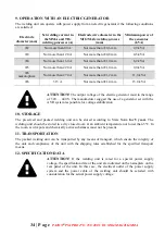
Page 32: ...ue a ON b OFF POWER OF PULSE Current pulse amplitude OFF default value a 0 OFF 80 positive or negative increment 1 FREQUENCY OF PULSE Current pulse frequency 50 Hz default value a 0 2 500 Hz positive...

Page 33: ...for PSI 270 PRO 400 V b 12 0 32 0 V krok zmiany 0 1 V for PSI 350 PRO 400 V BUTTON OF TORCH Mode on the torch button 2T default value a 2T b 4T c _4T INDUCTANCE Select one of three function levels OFF...

Page 34: ...onnect the power cable from the outlet of the power supply system Wait for about 5 minutes until static charges in the unit circuits disappear and then perform the maintenance operations After complet...

Page 35: ...manufacturer suggest the use of a generator set with the AVR system responsible for voltage stabilization 10 STORAGE The preserved and packed welding unit can be stored according to State Norm for 5 y...

Page 36: ...voltage for the semiautomatic arc welding process MIG MAG 12 29 V 12 30 V 13 DELIVERY SET 1 Welding unit with a power cable 3 m in length 1 pcs 2 Electrode wire feeding unit with rollers for wire 0 6...

Page 37: ...nt Cleaning should be carried out carefully keeping the compressor hose at a sufficient distance to avoid damage to the soldering of electronic components and mechanical parts Also the basic warranty...

Page 38: ...nly be used for the purposes for which it was created This appliance is intended for use by persons with the requisite qualifications It is the responsibility of the qualified personnel to install ser...

Page 39: ...ossible to each other ELECTRICAL SPARK MAY CAUSE FIRE OR EXPLOSIVES Flammable items should be removed from the workplace Do not perform welding work on containers that contain gases fuels oil products...

Page 40: ...cial Policy of 6 June 2014r Dz U 2014 pos 817 Pursuant to the Ordinance of the Minister of Health on Social Welfare dated 09 07 1996 OJ No 68 pos 194 The employer is required to carry out research and...

Page 41: ...40 P a g e PATON PSI PRO 270 350 400 V DC MIG MAG TIG MMA 17 ELECTRICAL SCHEMATIC DIAGRAM Basic electrical diagram Source PATON PSI 200 or 250 DC MIG MAG MMA TIG BIS 0403 BUV 0400 BVR 0400 V 400 V...

Page 42: ...______ signature of the seller Central PATON Service Center 14 Przemys owa Street Rzesz w City Poland zip code 35105 Head of Service Center Piotr B aszkowski Phone 48 22 290 86 96 e mail service paton...

Page 43: ...AND FAULTY CONDITION CAUSE Tel Technical support 48 22 290 86 96 Address of the service center 35105 Poland Rzesz w 14 Przemys owa Street DATE OF REPORT TO REPAIR DATE OF SERVICE REPAIR ______________...

Page 44: ...Y CONDITION CAUSE Tel Technical support 48 22 290 86 96 Address of the service center 35105 Poland Rzesz w 14 Przemys owa Street DATE OF REPORT TO REPAIR DATE OF SERVICE REPAIR ________________ ______...

Reviews: