5
ASSEMBLY INSTRUCTIONS
9-pin
Connector
Wire Connector
White to White
White to White
Black to Blue
Black to Black
A
B
7
Lock
Washer
Lock
Washer
Hex Nut
Hex Nut
A
B
5
6
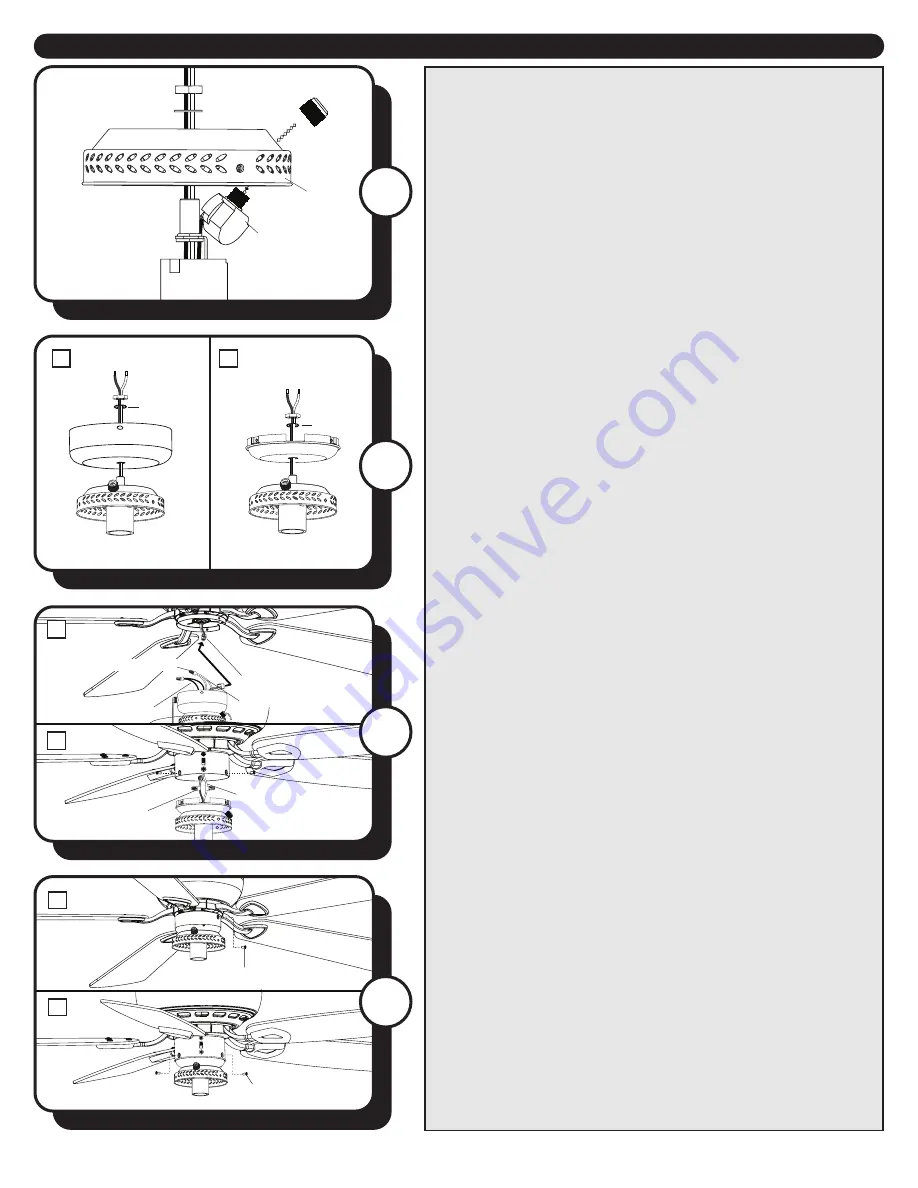
5. If the metal finish on the fitter cap does not match the
finish on the fan, install one of the extra fitter caps using
the steps that follow. Otherwise, skip to Step 6.
a. Remove the hex nut and star washer from the
threaded rod on the top of the LED fitter and remove the
cap from the light kit.
b. Unscrew and remove the pull chain ring from the
switch and remove the pull chain switch from the fitter
cap.
c. Select a fitter cap with the appropriate finish and
insert the wires from the light kit through the hole in
the center of the fitter cap. Secure with the star washer
and hex nut.
d. Insert the pull chain switch through the hole in the
side wall of the fitter cap and secure with pull chain ring.
6. Insert the threaded rod from the light kit through
the center hole in the switch housing (A) or the switch
housing cap (B). Secure it to the light kit using the lock
washer and hex nut from the hardware bag.
7. Use the wire connectors to connect the wires from the
LED fitter to the wires in the switch housing (A or B).
If your fan has a fitter plate (A), you may also need to
connect the 9-pin connector from the fan to the 9-pin
connector from the switch housing.
Note:
If your fan has two single-pin connectors extending
from the switch housing (B), it will be necessary to cut the
single-pin connectors off and strip 1/2” of insulation from
the end of the two wires in order to connect to the wires
of the light kit.
IMPORTANT:
DO NOT cut the wires to the
9-pin connectors.
A
B
Switch Housing Screw
Switch Housing Screw
8
8. Using the three previously removed switch housing
screws, re-attach the switch housing to the fitter plate (A)
or the switch housing cap to the switch housing (B).
Threaded Rod
Pull Chain Switch
Fitter Cap
Pull
Chain
Ring
Hex Nut
Star Washer
Socket


