
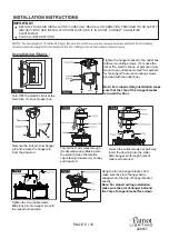
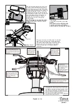
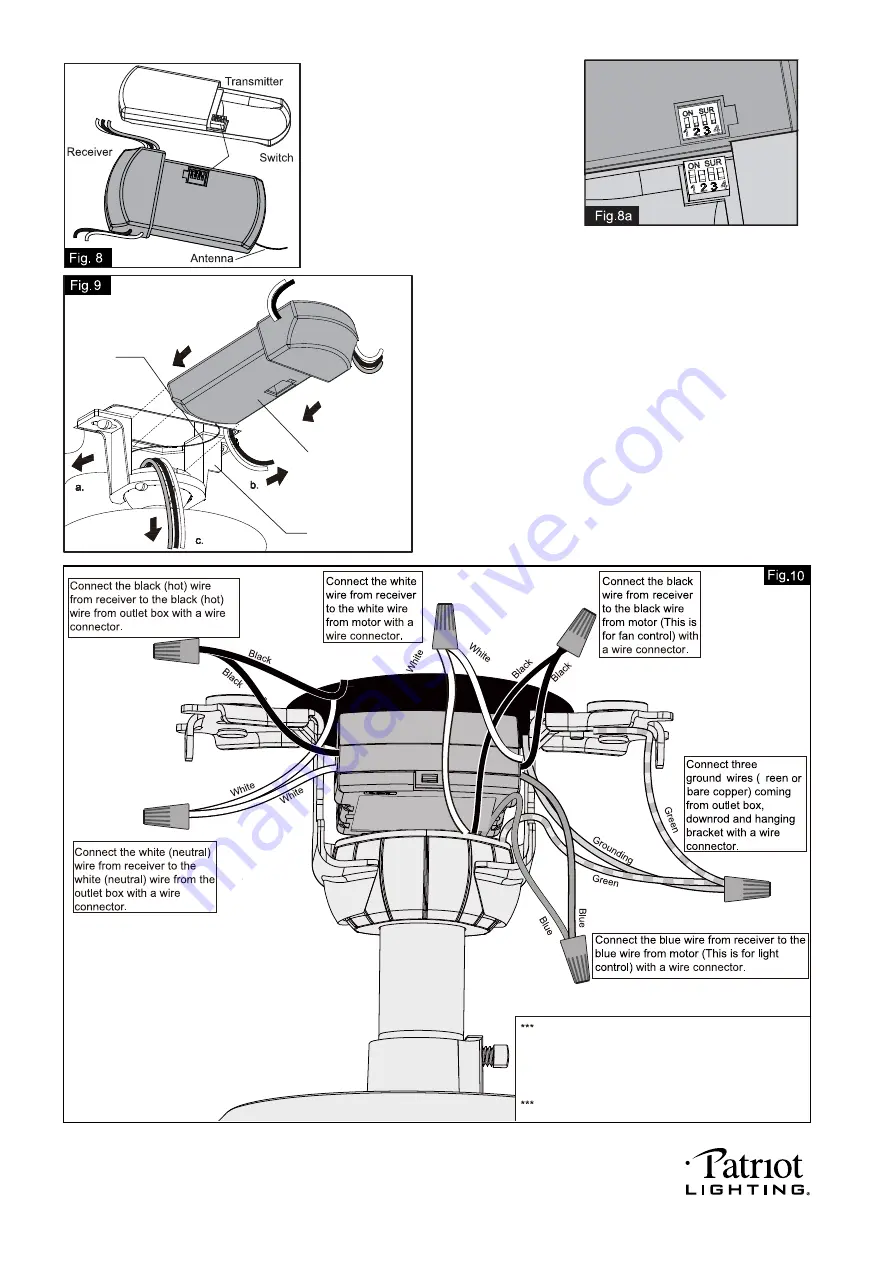
Move ground wires (a), outlet box wires (b), and motor
wires (c) away from the center of the hanger bracket.
Then slide receiver through hanger bracket as shown.
Antenna end first, until it is placed in the centered.
Finally, cut motor wires (c) to length needed for
connections.
G
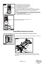
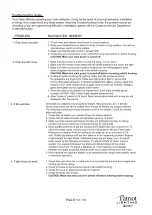
Code example:
1-ON 2-OFF 3-ON 4-OFF on both SUR
Switches.
Note: If you have two ceiling fans with
2 remote control units, set 2 different
codes for each set of transmitter / receiver.
Both the transmitter and receiver have a 4-key
unit code on each SUR Switch (Fig.8) and by
default, all keys are pre-set to the "off" position.
This means that the transmitter and receiver are
already paired together. However, if you have
multiple fans and remote controls and want to
avoid interference between them, you can "pair"
other transmitters and receivers together by
adjusting the SUR switches, so the same
numbered keys are in the "ON" position
on both (Fig.8a).
Note: The ceiling fan may work abnormally
if there is interference from other remote
controls.
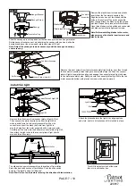
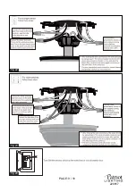
After making the wire connections, the wires should be
spread apart. The white (neutral) conductor from receiver
and outlet box with green (grounding) conductor on one
side; the black (hot) conductor from receiver and outlet
box with the white, black and blue conductor from receiver
and motor on the other side of the outlet box.
The wire connection points should be turned upward and
pushed carefully up into outlet box.
PAGE: 6 / 10
SUR
ON
SUR
ON
SUR
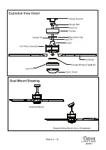
Receiver
Hanger Bracket
Antenna
220817
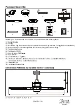
Summary of Contents for 355-0608
Page 1: ...PAGE 1 10 220817...
Page 3: ...PAGE 3 10 Connect Plate of Light Kit 220817...
Page 4: ...PAGE 4 10 220817...
Page 9: ...PAGE 9 10 Fig 22 Fig 23 Fig 24 220817...
Page 10: ...PAGE 10 10 220817...


