P-K Storm
TM
Gas Fired Boiler
Technical Service 1.877.728.5351
Revised: October 2, 2019
Released: October 2, 2019
Patterson-Kelley 2019
All Rights Reserved.
2691000099 P-K Storm Installation and Owners
Manual.docx
Page 42
3.9 Pre-Start Checklist
Before attempting to start the boiler, make sure the following items
have been completed.
Inspect the gas train, blower, ignition electrode, and boiler in general
to be sure there was no damage during shipment or installation.
Flue gas from the boiler is properly vented.
Gas connection has been made, pressure tested for leakage and the
line purged of air. Make sure all required vents have been installed.
Water connections are complete, and the boiler and system have
been filled and purged of air.
The boiler is connected to the correct electrical power source listed
on the nameplate, a disconnect having adequate overload protection is
required.
Combustion air openings are not obstructed in any way and have
adequate capacity.
The boiler is placed the proper distance from any combustible walls.
Relief valves have been piped to an acceptable drain at a safe point
of discharge.
Condensate piping is properly connected.
Verify system water quality is within specifications.
3.10 Safety Checks
The following checks of safety systems must be made before putting
the boiler into normal operation. Before firing the boiler refer to
Section
for information on the use of the controls, lighting, and
shut-down procedures.
Ignition Safety System Test
Test the ignition system safety shutdown as follows:
1. Cycle the boiler on by generating a heat request. (The
method for this will depend on your boiler configuration.)
2. During the pre-purge cycle (before ignition), smoothly close
the downstream manual isolation valve (inside the boiler
cabinet) to reduce the gas flow.
3. Closing the manual isolation valve will prevent a successful
ignition, and the NURO will display either:
109:
“Ignition Failed”
110:
“Ignition Failure Occurred”
These alarms indicate an ignition failure and the lockout will remain until the control is reset. After
completing this test, turn the boiler off, open the downstream manual isolation valve, then turn the boiler
back on.
Low Water Cut-Out Test
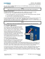
The boiler is furnished with a probe-type low water cut-
out. The probe is installed near the boiler’s
outlet in order to detect the presence of water at the highest possible location in the boiler and is
connected to the low water cut-out circuit board by a single wire. The low water cut-out circuit board is
located inside the boi
ler’s front door, toward the bottom left of the control panel and is identified with a
label.
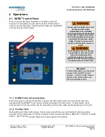
Never attempt to operate
a boiler that has failed to
pass all the safety
checks described below.
Operating a boiler that
has failed a safety check
could result in injury.
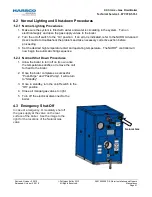
Bypassing safety
mechanisms will result
in unsafe boiler
operation which could
result in injury or death.
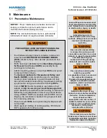
After checking controls
by manual adjustment,
make sure they are
always reset to their
proper settings.
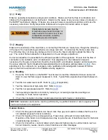
The user should become
thoroughly familiar with the
operation of the boiler and
controls before attempting to
make any adjustments.
Changing parameters
requires an understanding of
the parameters and the
functionality of the boiler.
The boiler may not function
properly if parameters are
changed from the factory
values.

