background image

P-K Storm

TM


Gas Fired Boiler 

Technical Service 1.877.728.5351


Revised: June 26, 2020 
Released: June 26, 2020 

©

 Patterson-Kelley 2020 

All Rights Reserved. 

2691000273 P-K Storm ST2500-ST4000 

Installation and Owners Manual Rev A.docx 

Page 53 


  Daily 

Observe operating temperature and general conditions.  Make sure that the flow of combustion and 
intake air to the appliance is not obstructed.  Determine the cause of any service codes or lockouts on 
the NURO

®

 touchscreen display.  Observe any unusual noises or operating conditions and make the 

necessary corrections.  Notify responsible individuals for required corrective action or repair. 


  Weekly 

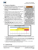
Observe the conditions of the main flame.  A normal high fire flame is mostly blue, though the refractory 
in the rear of the heat exchanger will glow an orange red color.  A normal low fire flame is also blue. 
The refractory may not show any orange-red color at low fire. Never 

attempt to adjust the flame “by 

eye”. The correct flame/combustion is dependent on the air and gas adjustment. 

Correct air adjustment is essential to the efficient operation of this appliance.  Ensure that the flow of 
combustion and ventilation air is not obstructed.  If an adjustment in the combustion appears 
necessary, the flue gas composition should be checked with a combustion analyzer and compared to 
the values stated in the Combustion Setup and Adjustment combustion settings table i

3.11.2

.


If an 

adjustment to the combustion is necessary, call a qualified and knowledgeable installer or service 
agency that has been trained on the Patterson-Kelley appliance. 

  Monthly  

1. 

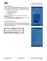
Press the “Info” button on the NURO

®

 touchscreen to load the Information Screen and scroll 

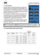
down to view the flame signal measured in Volts.  Typical flame signals should read between 8-
25V.   

2.  Test the low water level cut-off.  Refer to 

3.10.2

 (if applicable). 

3.  Test the manual reset high-temp limit.  Refer to 

3.10.4

. 

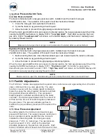
4.  Test the low gas pressure switch.  Refer to 

3.10.5

. 

5.  Test operating temperature controls by reducing or increasing temperature settings as 

necessary to check burner operation. 

6.  Check the combustion chamber condensate drain piping for leaks or obstructions. 


  Semi-Annually 

In addition to the recommended monthly service: 

1.  Check the burner for any accumulated dust or lint. You may clean the burner using only water to 

remove accumulated material.  Refer to 

5.2

. 

2.  Inspect burner for any signs of deterioration or corrosion.  Replace immediately if deterioration 

or corrosion is evident. 

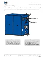
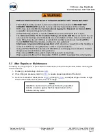
Check daily to be sure that the 
immediate area around the boiler or 
water heater is free and clear of any 
combustible materials, including 
flammable vapors and liquids. 

NOTICE!

  Installation and service must be performed by a qualified installer or service agency that 

has been trained on the appliance. 

Summary of Contents for STORM ST-2500

Page 1: ...Stroudsburg PA 18301 Telephone 570 476 7261 Toll Free 877 728 5351 Fax 570 476 724 www pattersonkelley com Released June 26 2020 INSTALLATION OW NE R S MANUAL INSTALLATION OW NE R S MANUAL INSTALLATIO...

Page 2: ...lation and lighting with a structure sufficiently strong and rigid to support the weight of the boiler all piping and accessories NOTICE Each safety device must be maintained and checked per the recom...

Page 3: ...fety precautions If any of the provisions of this manual are not fully and completely understood contact Patterson Kelley Technical Service at 570 476 7261 or toll free at 877 728 5351 Hazard Warnings...

Page 4: ...Explosion Hazards Do not store or use gasoline or other flammable vapors or liquids in the vicinity of this or any other gas fired appliance Burn hazard Possible hot surfaces Do not touch gas vent du...

Page 5: ...GAS PIPING CONSIDERATIONS 11 2 7 WATER QUALITY STANDARD 11 3 INSTALLATION 11 3 1 OVERVIEW 11 3 2 APPLIANCE CONNECTIONS 11 Appliance Connections ST 2500 ST 3000 12 Appliance Connections ST 3500 ST 400...

Page 6: ...h Tests 44 3 11 FUEL AIR ADJUSTMENTS 44 Gas Pressure Adjustment 44 Manual Control Mode for High and Low Fire Adjustment 45 Adjusting High Fire 46 Adjusting Low Fire 46 Checking Flame Signal 46 3 12 IN...

Page 7: ...al Gas 208 240 Volt 68 Natural Gas 480 Volt 70 Control Transformer Diagrams 72 6 3 BOILER PARTS IDENTIFICATION 74 Main Boiler Assembly ST 2500 ST 3000 74 Main Boiler Assembly ST 3500 ST 4000 75 Contro...

Page 8: ...tisfactory operation of any system Patterson Kelley cannot be responsible for the design or operation of such systems and a qualified engineer or contractor must be consulted If the information in thi...

Page 9: ...dust from RCFs and avoid contact with Skin or Eyes The National Institute for Occupational Safety and Health NIOSH recommends the use of a respirator meeting current standards to avoid inhalation of...

Page 10: ...mpletely understand the content please contact Patterson Kelley Technical Service at 570 476 7261 or toll free at 877 728 5351 1 2 Common Abbreviations Abbreviation Description AMP Ampere or Amperage...

Page 11: ...tain positive control of it at all times Do not attempt to move the boiler on surfaces that are not level Failure to heed this warning could result in personal injury or death NOTICE The boiler may be...

Page 12: ...t Setpoint 200 F Maximum Setpoint 185 F Installation of the boiler must conform to all the requirements of all national state and local codes established by the authorities having jurisdiction or in t...

Page 13: ...nected to the appliance Use a bubble level and make sure housekeeping pad is level before installation of appliance There are six 3 4 holes in the base which may be used for 5 8 anchor bolts Three of...

Page 14: ...he vent to combustible surfaces of 18 or as specified in the vent manufacturer s listed installation instructions The boiler must be installed in a space large in comparison to the boiler as described...

Page 15: ...or materials can result in serious injury or death due to fire or asphyxiation Before connecting a boiler to a venting system it must be determined whether the boiler is to be installed in a conventio...

Page 16: ...material is certified for Category II or IV operation NOTE For Category II installations ensure the flue venting system is designed to maintain a slightly negative exhaust pressure between 0 01 W C an...

Page 17: ...l from different manufacturers within the same system As per ANSI Z21 13b CSA 4 9b The use of cellular core PVC cellular core CPVC or Radel as venting materials is prohibited The use of external insul...

Page 18: ...irect Vent Sealed Combustion Systems Clearances The vent terminal shall be located at least 12 in from any air opening into a building The bottom of the vent terminal shall be at least 12 in above gra...

Page 19: ...mm above opening 6 in 15 cm for appliances 10 000 Btuh 3 kW 12 in 30 cm for appliances 10 000 Btuh 3 kW and 100 000 Btuh 30 kW 36 in 91 cm for appliances 100 000 Btuh 30 kW F Clearance to a mechanical...

Page 20: ...in efficient and function properly For more information refer to Patterson Kelley s Water Quality Standards for Hydronic Boilers in Multi Metal Systems in Appendix C Water Quality Standards Quality St...

Page 21: ...2020 Released June 26 2020 Patterson Kelley 2020 All Rights Reserved 2691000273 P K Storm ST2500 ST4000 Installation and Owners Manual Rev A docx Page 12 Appliance Connections ST 2500 ST 3000 All conn...

Page 22: ...2020 Released June 26 2020 Patterson Kelley 2020 All Rights Reserved 2691000273 P K Storm ST2500 ST4000 Installation and Owners Manual Rev A docx Page 13 Appliance Connections ST 3500 ST 4000 All conn...

Page 23: ...g nameplate of the Storm boiler to determine the required electrical service 208 240VAC three phase 60 hertz 440 480VAC three phase 60 hertz The incoming three phase power for the ST 2500 ST 4000 boil...

Page 24: ...T2500 ST4000 Installation and Owners Manual Rev A docx Page 15 Do not over tighten the hot lead terminal screws Maximum tightening torque 13 in lbs NOTE The hot lead terminals can accommodate maximum...

Page 25: ...ices such as damper limit switches control valve limit switches emergency stop buttons and low water cutoff devices This circuit is energized with 120VAC so the contacts on any auxiliary safety device...

Page 26: ...B2 14 The normally open contacts on these relays have a maximum voltage rating of 240VAC and maximum current capacity of 1 2 Amp Master Alarm Relay The Master Alarm Relay TB2 21 TB2 22 terminals are n...

Page 27: ...trols but generally closure of the Enable Disable circuit provides a call for heat to the boiler Opening this circuit prevents the boiler from running 4 20mA Analog Input TB1 3 and TB1 4 can be used t...

Page 28: ...esumes normal operation This circuit is energized by the boiler with a 5VDC potential so the contacts on the day night timer must be rated for minimum 5VDC 4 20mA Analog Output TB1 15 and TB1 16 provi...

Page 29: ...municate directly with the outdoors or through a vertical or horizontal duct that communicates to the outdoors Minimum free area of the opening is 1 square inch for each 3 000 Btu Hr 700 mm2 kW of ins...

Page 30: ...graph A C When combustion air is supplied by natural airflow into a space containing the type of appliance described in Paragraph B the cross sectional area of the opening shall not be less than the s...

Page 31: ...ice insects etc The combustion air supply must be free from dust lint etc The presence of such materials in the air supplied to the burner could cause nuisance Low Air shutdowns or premature burner fa...

Page 32: ...ends and most installation codes require the use of motorized combustion air dampers with end limit switches installed in the combustion air intake ductwork upstream of each appliance This damper isol...

Page 33: ...rom the appliance itself All end limit switches must be rated for 120VAC External power supplies are required for Relay A Relay B Relay C and Relay D Because power is provided from an external source...

Page 34: ...not be responsible for the effects such adverse conditions may have on the operation of the appliances Vertical vents are allowed to be terminated with a variety of ends including plain straight pipe...

Page 35: ...ow table for vent design parameters P K STORM Boiler Model Draft Stack Temperature CO2 Natural Gas ST 2500 ST 3000 ST 3500 ST 4000 Category II 0 01 to 0 05 W C 220 F gross 8 75 ST 2500 ST 3000 ST 3500...

Page 36: ...control the exhaust back pressure within the appliance and upstream of this damper The 0 04 W C in the common flue will also help make sure the exhaust gases from an online appliance does not backflow...

Page 37: ...le configurations of vent and air intake terminations are illustrated below The combined pressure drop of the air supply duct and exhaust vent must not exceed 0 44 W C This pressure drop includes both...

Page 38: ...0 01 W C and 0 05 W C NOTE For Category IV installations ensure the flue venting system is designed to maintain a slightly positive exhaust pressure which MUST BE in the following ranges 0 01 W C and...

Page 39: ...ly negative exhaust pressure between 0 01 W C and 0 05 W C NOTE For Category IV installations ensure the flue venting system is designed to maintain a slightly positive exhaust pressure which MUST BE...

Page 40: ...June 26 2020 Patterson Kelley 2020 All Rights Reserved 2691000273 P K Storm ST2500 ST4000 Installation and Owners Manual Rev A docx Page 31 When terminating on the same vertical axis the air intake m...

Page 41: ...a vent temperature that may cause excessive condensate production in the vent There are several requirements for reliable operation of the boilers under Category II conditions 1 A normally closed moto...

Page 42: ...ensure that any and all integral gasketing is properly assembled and creates a gas and water tight seal Systems that require silicone caulking for gasketing should only be installed with silicone caul...

Page 43: ...e and make certain the end of the drain line is not submerged or otherwise blocked 3 All condensate plumbing must be protected from freezing Do not locate the condensate piping such that an ice dam of...

Page 44: ...Fired Boiler Technical Service 1 877 728 5351 Revised June 26 2020 Released June 26 2020 Patterson Kelley 2020 All Rights Reserved 2691000273 P K Storm ST2500 ST4000 Installation and Owners Manual Rev...

Page 45: ...mmer exhaust fan Close fireplace dampers 4 Place the appliance being inspected in operation Follow the lighting instructions Adjust the thermostat so that the appliance will operate continuously 5 Tes...

Page 46: ...s than 14 W C Refer to the table below or the appliance s label for the minimum inlet gas pressure ST 2500 ST 3000 ST 3500 ST 4000 Natural Gas 3 5 W C 3 5 W C 3 5 W C 3 5 W C This unit comes with a se...

Page 47: ...00 3250 2650 2280 4 4 026 10 1 20 2 15800 10900 8800 7500 6700 5500 4600 Pressure Testing the Gas Piping The appliance and all gas piping connections should be pressure tested and must be checked for...

Page 48: ...be exposed to refrigerated air circulation must be equipped with flow control valves or other automatic means to prevent gravity circulation of the boiler water during the cooling cycle NOTICE Condens...

Page 49: ...ef valve must be vertical The ASME Section IV relief valves are available for purchase from Patterson Kelley Low Water Cut Off The boiler is furnished with a probe type low water cut off no field pipi...

Page 50: ...revent gravity circulation of the boiler water during the cooling cycle 3 8 Water Quality The P K Storm boiler s heat exchanger is made of a stainless steel alloy The heat exchanger requires proper wa...

Page 51: ...ler on by generating a heat request The method for this will depend on your boiler configuration 2 During the pre purge cycle before ignition smoothly close the downstream manual isolation valve insid...

Page 52: ...Test The boiler is furnished with two manual reset high temperature limits Both probes are installed near the boiler s outlet in order to measure the outgoing supply water temperature Each probe is co...

Page 53: ...hutoff control valve opens to attempt ignition the high gas pressure switch will trip causing the NURO touchscreen to display 10011 High Gas Limit Even after re opening the downstream gas cock inside...

Page 54: ...e used when adjusting or tuning the gas safety shut off control valve Once in Manual Control Firing Rate mode a heat request is required Once the appliance cycles on and is running in Manual Control F...

Page 55: ...tem Set boiler to the Manual Control Firing Rate mode as described above and decrease the firing rate to 0 Once the boiler has reached low fire operation check combustion readings using the combustion...

Page 56: ...gh of the complete control setup please refer to the NURO Boiler Controller Advanced User s Guide Part Number is 1004905979 which is helpful for more complex installations For more complex boiler or w...

Page 57: ...Temperature Inlet Return Temperature Exhaust Temperature Firing Rate etc Pressing the Info button in the lower left corner will load the Information screen For the setup wizard press the Settings but...

Page 58: ...also allows the user to back track at any time by pressing PREVIOUS in the bottom left corner of the screen The Setup Wizard allows the user to assign functionality to the user configurable Relays A...

Page 59: ...he clasp and swinging open to the left Factory Tests Safe lighting and other performance criteria were met with the gas manifold and control assembly provided on this boiler when the boiler underwent...

Page 60: ...eshoot the problem and take necessary corrective action before proceeding 3 Set the desired high temperature limit and operating temperature The NURO controller will now begin the automatic firing seq...

Page 61: ...clear of any combustible materials including flammable vapors and liquids NOTICE Proper maintenance schedule and record keeping is critical for optimum performance and to maintain the Patterson Kelle...

Page 62: ...analyzer and compared to the values stated in the Combustion Setup and Adjustment combustion settings table in 3 11 2 If an adjustment to the combustion is necessary call a qualified and knowledgeable...

Page 63: ...g that procedure Patterson Kelley recommends annual maintenance and cleaning of the heat exchanger to be done simultaneously Please refer to Section 5 2 for more information NOTE This section recommen...

Page 64: ...e procedure in 5 2 Drain and flush the water side of the heat exchanger as required separate from system flush using clean water only This heat exchanger comes with a drain valve it is located on the...

Page 65: ...eplace them with new media 7 Examine the venting system Refer to the vent manufacturer s instructions for requirements in addition to those listed below a Check all joints and pipe connections for tig...

Page 66: ...e the surrounding area is free of obstacles 5 Disconnect the wires to the sensors switches ignition electrode and the ionization rod Secure the wires out of the way for the following steps 6 Remove th...

Page 67: ...to the left of the door that locks the hinge in place Once the pin is removed the door will be free to rotate about the hinge providing better access to the inside of the heat exchanger BE CAREFUL NOT...

Page 68: ...FRACTORY OR THE INNER EXCHANGER REFRACTORY WET 12 Use a pressurized water hose with control nozzle Begin by spraying just a few seconds of water into the combustion chamber and then close off the nozz...

Page 69: ...Be sure to have replaced both the top gasket and the burner door gasket b Align the studs on the burner door first and then align the 2 back studs on the blower plate second Rest the casting on the bu...

Page 70: ...uct contains a Combustion Area lined with REFRACTORY CERAMIC FIBERS RCFs similar to many other devices produced in this industry RCFs have been identified by the International Agency for Research on C...

Page 71: ...d the CH LOW FIRE HOLD TIME timer is started Once the LOW FIRE HOLD TIME timer expires the boiler is released to modulation 7 The NURO Control modulates the firing rate between low and high fire to ma...

Page 72: ...lock the boiler out When proper gas pressure is restored and the on screen reset button is pressed the boiler will reset and resume the sequence of operation at Step 3 5 4 High Gas Pressure The high g...

Page 73: ...Run is displayed the boiler lost the flame signal during operation Check that combustion is adjusted properly the gas pressure is correct and the ignition electrode ignition wire and gas valve are fun...

Page 74: ...available by calling or visit the Patterson Kelley website www pattersonkelley com When ordering replacement parts please have the model number and serial number of your boiler available Typical schem...

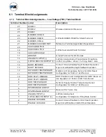
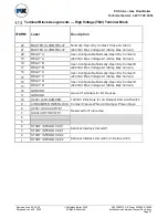
Page 75: ...UT 4 20mA Analog Output Tracks Boiler Firing Rate 100 Firing Rate 20mA 1 Firing Rate 4mA 15 4 20mA ANALOG OUTPUT 14 NIGHT SETBACK Contact Closure Enables Night Setback Operation Open Circuit Disables...

Page 76: ...RELAY A 18 RELAY B User Configurable Normally Open Dry Contact B 240VAC Max Voltage 1 2Amp Max Current 17 RELAY B 16 RELAY C User Configurable Normally Open Dry Contact C 240VAC Max Voltage 1 2Amp Ma...

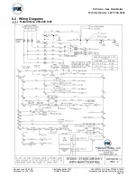
Page 77: ...Service 1 877 728 5351 Revised June 26 2020 Released June 26 2020 Patterson Kelley 2020 All Rights Reserved 2691000273 P K Storm ST2500 ST4000 Installation and Owners Manual Rev A docx Page 68 6 2 Wi...

Page 78: ...Fired Boiler Technical Service 1 877 728 5351 Revised June 26 2020 Released June 26 2020 Patterson Kelley 2020 All Rights Reserved 2691000273 P K Storm ST2500 ST4000 Installation and Owners Manual Rev...

Page 79: ...er Technical Service 1 877 728 5351 Revised June 26 2020 Released June 26 2020 Patterson Kelley 2020 All Rights Reserved 2691000273 P K Storm ST2500 ST4000 Installation and Owners Manual Rev A docx Pa...

Page 80: ...Fired Boiler Technical Service 1 877 728 5351 Revised June 26 2020 Released June 26 2020 Patterson Kelley 2020 All Rights Reserved 2691000273 P K Storm ST2500 ST4000 Installation and Owners Manual Rev...

Page 81: ...351 Revised June 26 2020 Released June 26 2020 Patterson Kelley 2020 All Rights Reserved 2691000273 P K Storm ST2500 ST4000 Installation and Owners Manual Rev A docx Page 72 Control Transformer Diagra...

Page 82: ...d Owners Manual Rev A docx Page 73 440 480 VAC Three Phase 60 Hz Before making any electrical connections to the boiler verify that the control transformer is properly configured for the applicable in...

Page 83: ...77 728 5351 Revised June 26 2020 Released June 26 2020 Patterson Kelley 2020 All Rights Reserved 2691000273 P K Storm ST2500 ST4000 Installation and Owners Manual Rev A docx Page 74 6 3 Boiler Parts I...

Page 84: ...ical Service 1 877 728 5351 Revised June 26 2020 Released June 26 2020 Patterson Kelley 2020 All Rights Reserved 2691000273 P K Storm ST2500 ST4000 Installation and Owners Manual Rev A docx Page 75 Ma...

Page 85: ...oiler Technical Service 1 877 728 5351 Revised June 26 2020 Released June 26 2020 Patterson Kelley 2020 All Rights Reserved 2691000273 P K Storm ST2500 ST4000 Installation and Owners Manual Rev A docx...

Page 86: ...al Service 1 877 728 5351 Revised June 26 2020 Released June 26 2020 Patterson Kelley 2020 All Rights Reserved 2691000273 P K Storm ST2500 ST4000 Installation and Owners Manual Rev A docx Page 77 Heat...

Page 87: ...al Service 1 877 728 5351 Revised June 26 2020 Released June 26 2020 Patterson Kelley 2020 All Rights Reserved 2691000273 P K Storm ST2500 ST4000 Installation and Owners Manual Rev A docx Page 78 Heat...

Page 88: ...ler Technical Service 1 877 728 5351 Revised June 26 2020 Released June 26 2020 Patterson Kelley 2020 All Rights Reserved 2691000273 P K Storm ST2500 ST4000 Installation and Owners Manual Rev A docx P...

Page 89: ...echnical Service 1 877 728 5351 Revised June 26 2020 Released June 26 2020 Patterson Kelley 2020 All Rights Reserved 2691000273 P K Storm ST2500 ST4000 Installation and Owners Manual Rev A docx Page 8...

Page 90: ...echnical Service 1 877 728 5351 Revised June 26 2020 Released June 26 2020 Patterson Kelley 2020 All Rights Reserved 2691000273 P K Storm ST2500 ST4000 Installation and Owners Manual Rev A docx Page 8...

Page 91: ...d facility for repairs of any products or party alleged defective shall in all events be at Buyer s sole risk and cost This warranty applies only if the original installer and Seller Attention Patters...

Page 92: ...ulting in whole or in part from any modification or alteration Buyer makes to any product sold hereunder and N Design defects where Seller has complied with Buyer s design specifications III PROOF OF...

Page 93: ...___ w c Lockup Static Gas pressure Gas pressure drop ignition _____ 2 Water Inlet temperature _____ F 3 Water Outlet temperature _____ F 4 Flow through boiler _____ GPM 5 Operating Temperature Setpoin...

Page 94: ...5351 Revised June 26 2020 Released June 26 2020 Patterson Kelley 2020 All Rights Reserved 2691000273 P K Storm ST2500 ST4000 Installation and Owners Manual Rev A docx Page 85 Appendix A Maintenance Lo...

Page 95: ...ndix B Boiler Altitude Derate Schedule For installations over 2 000 ft elevations a derate schedule is applied The boiler input rating must be reduced by 4 per 1 000 ft which is illustrated in the gra...

Page 96: ...d more than 10 of the system volume per year and meter readings should be recorded at least monthly to ensure system losses are minimized and corrective actions shall be taken when needed Treatment pr...

Page 97: ...rough estimate of the total system volume during the initial fill In general the annual amount of fresh water make up should be less than 10 of the total system volume A water meter can also be usefu...

Page 98: ...orating piping fittings or legacy boiler s heat exchangers Patterson Kelley recommends installing a side stream filter maximum 10 micron to remove this existing particulate sediment etc There are many...

Page 99: ...d gas pipe sizing Electrical Power Supply Carefully inspect the boiler s nameplate labels which describe the power supply requirements Provide an appropriate power feed to the boiler with overcurrent...

Page 100: ...s couplings flanges etc P K STORM ST 2500 through ST 4000 Boilers Minimum Maximum Flow Rates Flow Condition Boiler Operation Flow Rate Approximate T ST 2500 ST 3000 ST 3500 ST 4000 Maximum Flow High F...

Page 101: ...ST 2500 ST 3000 ST 3500 ST 4000 Mixture Flow Pressure Flow Pressure Flow Pressure Flow Pressure 0 243 GPM 17 0 ft 291 GPM 24 4 ft 340 GPM 19 7 ft 388 GPM 25 7 ft 10 246 GPM 17 4 ft 295 GPM 25 0 ft 34...

Reviews: