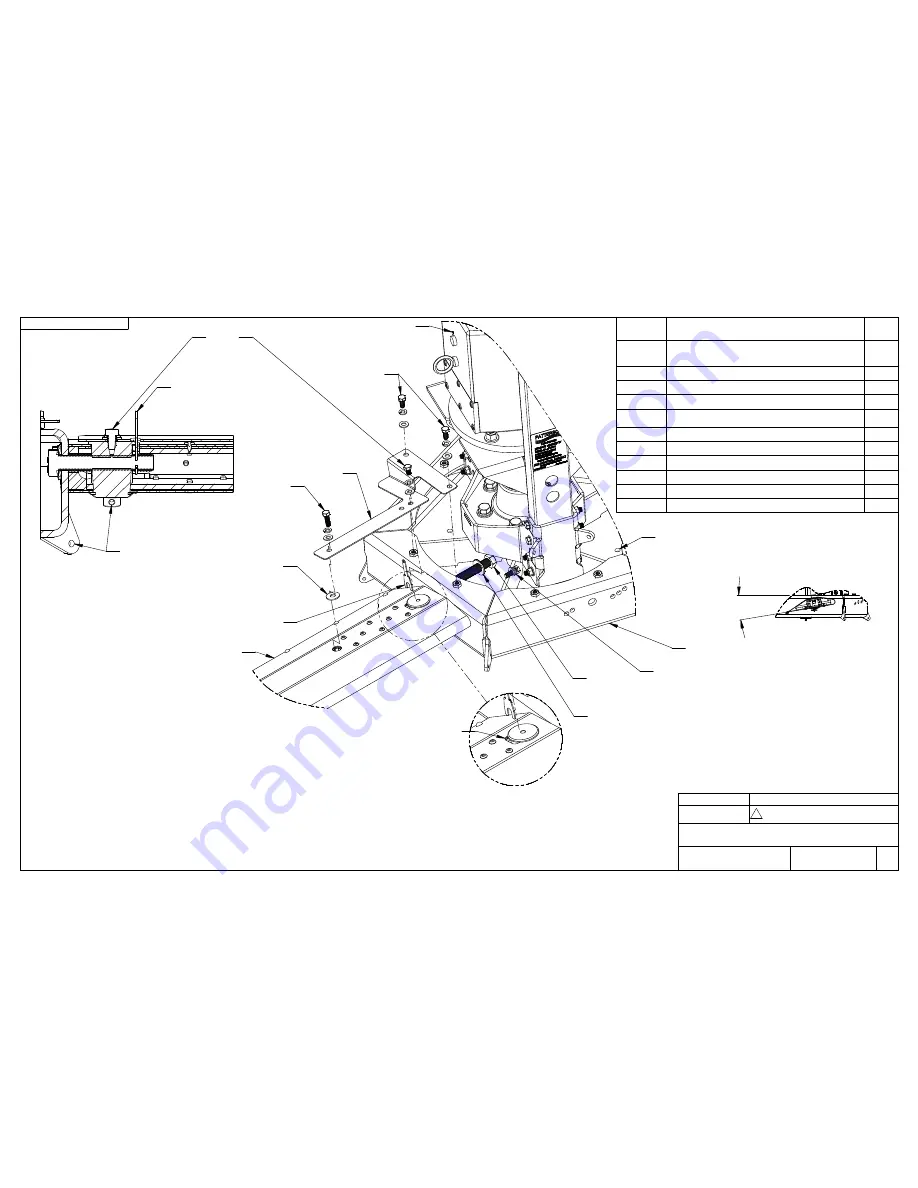
background image

INSTALLATION NOTES:

INSTALL THE BLADE ASSY, BOLTS AND SAFETY LOCK (SEE SECTION VIEW)

1.

ADD THE SAFETY PLATES

2.

FIT THE BLADE SAFETY CABLE (SEE VIEW C ON PAGE 12).

3.

REMOVE PLUG IN CAP OF GEARBOX BEFORE USE

4.

BLADE SAFETY LOCK MUST ALWAYS BE IN PLACE WHEN FAN IS OPERATING SEE SECTION 

5.

VIEW FOR INSTALLATION DETAIL. IF LOST OR BROKEN, CAN BE REPLACED BY MCMASTER 

CARR # 98407A138

REMOVE PLASTIC FILM ON BLADES AFTER INSTALLATION

6.

2 HP FAN POWER UNIT KIT #203194 MATCH WITH 24' FAN BLADE SET #201259

7.

1 HP FAN POWER UNIT KIT #203530 MATCH WITH 18' FAN BLADE SET #202360 OR 20' FAN 

8.

BLADE SET #202359

5/8-11 BOLT SHOULD BE TIGHTENED TO 120 LB-FT

9.

5/16-18 BOLTS SHOULD BE TIGHTENED TO 15 LB-FT

10.

SECTION VIEW

202674

203584

203410

NOTE 10

WARNINGS:
-FOR INDUSTRIAL USE ONLY
-AN ELECTRIC DRIVE MUST BE USED TO CONNECT THE FAN (SOLD SEPARATELY)

PART 

NUMBER

DESCRIPTION

QTY

201895

202361

202294

FAN HVLS 24' BLADE ASSY (SET #201259)

FAN HVLS 20' BLADE ASSY (SET #202359)

FAN HVLS 18' BLADE ASSY (SET #202360)

5

201988

FAN HVLS 5/8-11X3:1/2'' BLADE BOLT

5

200153

BELLEVILLE SPRING LOCK WASHER 5/8"

5

203135

HEX BOLT 5/16-18 NC X 1" LG Z/P GR 5

10

201972

HEX BOLT 5/16-18 NC X3/4" LG Z/P GR 5

(BOLTED ON 203193)

10

202674

HEX BOLT 5/16-18 NC X 1/2" LG Z/P GR5

5

203584

LOCK WASHER 5/16 HEAT TREATED

25

203410

WASHER 5/16 GR 8

25

202048

FLAT WASHER 5/16 (ALUMINIUM)

5

201864

FAN HVLS BLADE SAFETY PLATE

5

203692

FAN HVLS 5/8-11 BOLT SAFETY LOCK

5

NUMBER

NUMÉRO

:

P-24872

PAGE 13

FAN HVLS BLADES INSTALLATION INSTRUCTIONS

3

DATE (Y/M/D) :

PAR / BY :

DESCRIPTION

RÉVISION / REVISION

TITLE

TITRE :

P/N 203623
DWG P-24872

REVISION

RÉVISION

3

2013-04-11

SAME AS REV 2

P.F.

 10° REF 

203692

NOTE 3

PASS THRU THIS HOLE TO 

INSTALL 203692 IN 5/8-11 BOLT SLOT

203135

IF DRAINING HOLES NEED TO BE PLUGGED, 

USE MCMASTER-CARR PLUG # 

201864

203584

203135

2598K21,9191T31 OR 9545K51

NOTE 10

203410

NOTE 10

(2x)

NOTE 10

203410

NOTE 9

201988

203584

THE BOLT HEAD

202048

CONVEX SIDE MUST BE AGAINST

(FRAME ASSY FROM SET #203194)

203193

NOTE 5

NOTE 4

203692 (BLADE BOLT SAFETY LOCK)

200153

201972

203584

203410

BLADE

201895,

202361 OR

202294

Summary of Contents for HIGH-5

Page 1: ...HIGH 5 High Volume Ceiling Fan Installation Manual Blythewood SC 29016 800 768 3985 www pattersonfan com...

Page 2: ...ev 3 Page 4 Addendum To High 5 Installation Instructions Mechanical Only Please Note This document is meant to be used in conjunction with the Installation Instruction drawings that accompany this uni...

Page 3: ...oid the manufacturer s warranty FAN SPACING PLACEMENT AND CLEARANCE Fans should be mounted such that the blades are a minimum of 10 feet above the floor Also ensure that the fan blades have a clearanc...

Page 4: ...re proper lubrication Grease type is Mobil Unirex EP2 Add grease as needed filling slowly until grease passes through the upper seal hole Mounting Hardware All nuts and bolts related to mounting of th...

Page 5: ...rdware using the downrod clamp see page 11 of the Installation Instructions Step 2 Attach Fan Assembly to Mounting Hardware Reference Page 12 View A of the High 5 Installation Instructions A Using a s...

Page 6: ...nstall the guy wires may void the manufacturer s warranty The following steps should be performed with the aid of a scissor lift A Open the quick link located on the fan assembly Slide one eye of the...

Page 7: ...ll the way C Pitch the leading edge of the blade up Insert the 5 16 18 NC x 1 bolt with necessary washers through the fan hub and into the corresponding hole in the fan blade Tighten and secure this b...

Page 8: ...ternately through the holes at the corners of the fan hub pentagon and the holes of the blade pins see page 12 view C B Overlap the wire and clamp it together using 3 saddle clamps in the manner shown...

Page 9: ...BEFORE INSTALLING THE FAN ENSURE THAT THE STRUCTURE WHERE IT WILL BE FIXED IS SOLID ENOUGH TO SUPPORT THE LIVE LOAD OF IT SEE SPECIFICATIONS SHEET SECURE THE PRE ASSEMBLED INSTALLATION SUPPORT TO THE...

Page 10: ...IEW B 169735 202837 VIEW A 165710 4x INSTALLATION OF THE FRAME SAFETY CABLE 202164 THE WIRE ROPE PASSES OVER THE H BEAM AND THRU THE HOLES IN THE VERTICAL TUBES SADDLE CLIPS 187108 SHOULD BE INSTALLED...

Page 11: ...ASSY SET 202359 FAN HVLS 18 BLADE ASSY SET 202360 5 201988 FAN HVLS 5 8 11X3 1 2 BLADE BOLT 5 200153 BELLEVILLE SPRING LOCK WASHER 5 8 5 203135 HEX BOLT 5 16 18 NC X 1 LG Z P GR 5 10 201972 HEX BOLT 5...

Page 12: ...48510 FAN HVLS UPPER HUB BEARING CUP 1 13 163017 163016 25580 FAN HVLS BOTTOM HUB BEARING 25520 FAN HVLS BOTTOM HUB BEARING CUP 1 14 195376 FAN HVLS MAIN FRAME HUB H 618 GREASE FITTING BEARING CUPS IN...

Page 13: ...FOR COUPLING 1 18 145482 5016 WITH TWO SEALS COVER 1 19 110104 1 4 SQUARE KEY X 1 1 2 LG 2 20 203207 FAN HVLS 1 3 8 12 SLOTTED NUT MODIFIED 1 21 201896 FAN HVLS BLADES HUB WELDMENT 1 22 201972 HEX BO...

Page 14: ...MOVE FREELY ITEM NO PART NUMBER DESCRIPTION QTY 1 201845 FAN HVLS INST SUPPORT WELDMENT 1 2 201836 FAN HVLS INST SUPPORT TUBE ON CROSS MEMBER 1 3 202047 FAN HVLS INST SUPPORT BEAM SHIM 2 4 201839 FAN...

Page 15: ...1 4 SADDLE CLIP ZINC PLATED 4 8 201971 HEX BOLT 3 8 16 NC X 4 1 4 LG Z P GR 5 2 9 203412 WASHER 3 8 GR 8 13 32X13 16X 05 08 4 10 110665 NYLON INSERT LOCKNUT 3 8 16 Z P GR 5 2 11 169735 1 4 EYE EYE TUR...

Page 16: ...ALL OLD FASTENERS FOR SAFETY PURPOSE 3 ITEM NO PART NUMBER DESCRIPTION QTY 1 201895 FAN HVLS BLADE 24 ASSY WITH WINGLET 1 2 201863 FAN HVLS BLADE SHAFT SUPPORT 1 3 201965 FAN HVLS BLADE WINGLET SPARE...

Page 17: ...HVLS BLADE SAFETY PLATE 1 5 201988 FAN HVLS 5 8 11X3 1 2 BLADE BOLT 1 6 200153 BELLEVILLE SPRING LOCK WASHER 5 8 1 7 202674 HEX BOLT 5 16 18 NC X 1 2 LG Z P GR5 1 8 201972 HEX BOLT 5 16 18 NC X 3 4 LG...

Page 18: ...D ALL OLD FASTENERS FOR SAFETY PURPOSE 3 ITEM NO PART NUMBER DESCRIPTION QTY 1 202294 FAN HVLS BLADE 18 ASSY WITH WINGLET 1 2 201863 FAN HVLS BLADE SHAFT SUPPORT 1 3 201965 FAN HVLS BLADE WINGLET SPAR...

Reviews: