


32
33
32
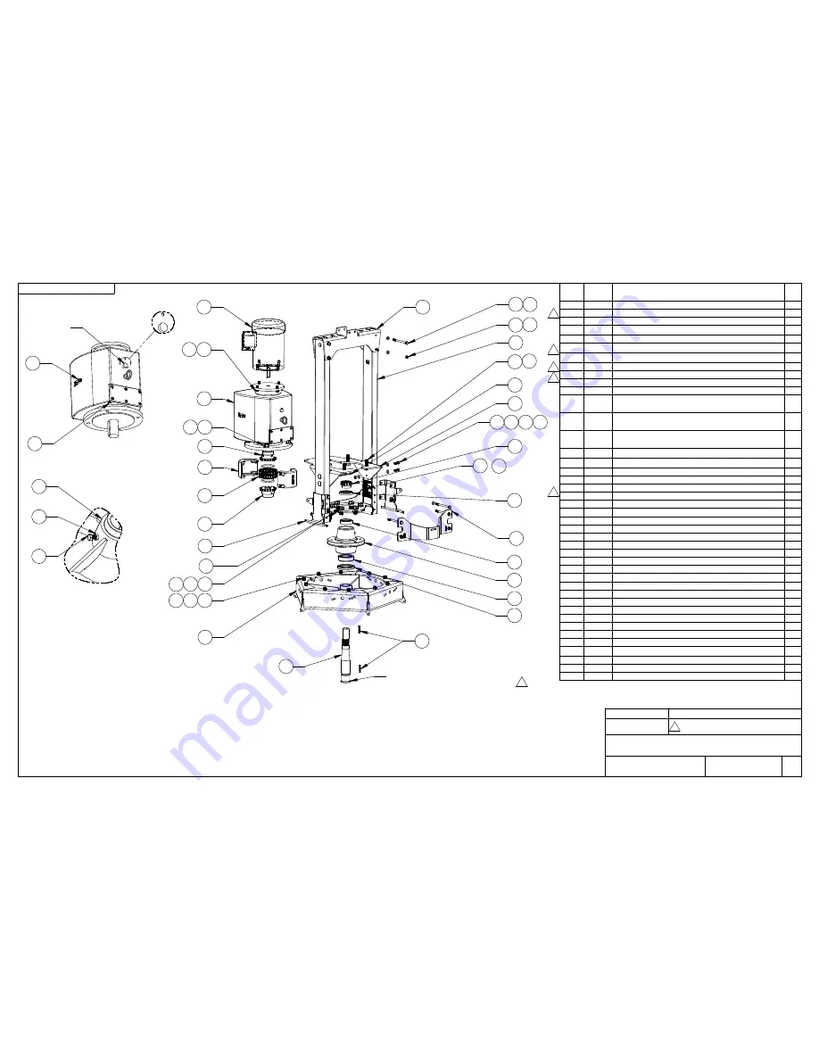
(DRAIN HOLE)
(OIL LEVEL)
32
3
3
3
3
3
37
32 29
MAINTENANCE INFORMATION:
-GEAR BOX OIL: CHEVRON DELO GEAR ESI 85W-140
-FILL TO OIL LEVEL PORT
-PATTERSON RECOMMENDS CHECKING AND CHANGING OIL ANNUALLY.
HOWEVER, FAILURE TO DO SO DOES NOT VOID THE WARRANTY.
-HUB GREASE: MOBIL UNIREX EP2
-FILL SLOWLY UNTIL GREASE PASSES THROUGH UPPER SEAL HOLE
-BOLTS & NUTS TIGHTENING MUST BE INSPECT ANNUALLY,
IF REMOVED, USE APPROPRIATE TORQUE:
-5/16-18 BOLTS RECOMMENDED TORQUE: 15 LB-FT
-3/8-16 BOLTS RECOMMENDED TORQUE : 25 LB-FT
-1/2-13 BOLTS RECOMMENDED TORQUE : 60 LB-FT
-9/16-18 BOLTS RECOMMENDED TORQUE: 90 LB-FT
-1/2-13 SET SCREWS IN COUPLING RECOMMENDED TORQUE: 50 LB-FT
ITEM
NO.
PART
NUMBER
DESCRIPTION
QTY
1
201874
FAN HVLS MAIN FRAME TOP CROSSMEMBER
1
2
204519
FAN HVLS MAIN FRAME TUBE (SOLD IN PAIR)
2
3
201881
FAN HVLS MAIN FRAME HUB SUPPORT PLATE
1
4
201882
FAN HVLS MAIN FRAME HUB SUPPORT SIDE PLATE
2
5
201880
FAN HVLS MAIN FRAME SAFETY PLATE
2
6
202492
FAN HVLS MAIN FRAME GEARBOX SUPPORT PLATE
1
7
201573
EM-AC-1HP18F56C-208-230/460/3/60-TEFC - 1 HP MOTOR
1
8
202503
RH-565-36:1-1:3/8-56C-C-PF-VB - GEARBOX
1
9
204520
FAN HVLS MAIN FRAME AXLE K1/4
1
10
204673
2-2.716-.375(TB)-W/HOLE - UPPER SHAFT SEAL
1
11
201713
2.375-3.543-.375(TA) - BOTTOM SHAFT SEAL
1
12
154936
154931
LM48548 - FAN HVLS UPPER HUB BEARING
LM48510 - FAN HVLS UPPER HUB BEARING CUP
1
13
163017
163016
25580 - FAN HVLS BOTTOM HUB BEARING
25520 - FAN HVLS BOTTOM HUB BEARING CUP
1
14
195376
FAN HVLS MAIN FRAME HUB H-618 (GREASE FITTING &
BEARING CUPS INSTALLED)
1
15
143975
5016H1:5/8K3/8-2S3/8-24-W/S - UPPER CHAIN COUPLING
1
16
178992
FAN HVLS BLADE SUPPORT STIFFENER
1
17
104733
5016(INCL. 1 C/L) - CHAIN FOR COUPLING
1
18
145482
5016(WITH TWO SEALS) - COVER
1
19
110104
1/4" SQUARE KEY X 1:1/2" LG
2
20
203207
FAN HVLS 1:3/8-12 SLOTTED NUT - MODIFIED
1
21
201896
FAN HVLS BLADES HUB WELDMENT
1
22
201972
HEX BOLT 5/16-18 NC X 3/4" LG Z/P GR 5
10
23
203135
HEX BOLT 5/16-18 NC X 1" LG Z/P GR 5
4
24
200572
HEX BOLT 5/16-18 X 1-1/4" Z/P GR 5
1
25
203651
HEX BOLT 5/16-18 NC X 4:1/4" LG Z/P GR 5
12
26
155684
HEX BOLT 3/8-16 X 1" LG Z/P GR 5
4
27
201970
HEX BOLT 1/2-13 NC X 1 3/4" LG Z/P GR 5
4
28
203167
HEX BOLT 9/16-18 X 1-1/2" Z/P GR 5
6
29
183038
NYLON INSERT LOCKNUT 5/16-18 Z/P GR 5
16
30
110667
NYLON INSERT LOCKNUT 1/2-13 Z/P GR 5
4
31
202604
HEX JAM NUT 5/16-18 Z/P GR2
1
32
203410
WASHER 5/16 GR 8 (11/32X11/16X.05-.08)
42
33
203408
WASHER 1/2 GR8 (17/32 X 1:1/16 X .09-.18)
8
34
203409
WASHER 9/16 GR8 ( 19/32X1:5/32 X .09-.13)
6
35
203584
LOCK WASHER 5/16 HEAT TREATED
10
36
203583
LOCK WASHER 3/8 HEAT TREATED
4
37
203581
LOCK WASHER 9/16 HEAT TREATED
6
38
203221
COTTER PIN Ø1/8" X2:1/2" LG
1
39
202844
PLUG M(NPT1/4-19)-MAGNETIC-ACIER-SOCKET HEAD
1
40
203700
PLUG M(NPTF1/4-18)-MAGNETIC-ACIER-SQ.HEAD
1
41
203622
FAN HVLS MAINTENANCE STICKER
1
42
204288
STICKER FOR FAN HVLS DRIVE 1HP #203530
1
NUMBER
NUMÉRO
:
P-24872
PAGE 15
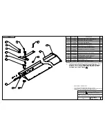
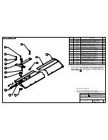
FAN HVLS PU 1HP (203531) PARTS LIST
3
DATE (Y/M/D) :
PAR / BY :
DESCRIPTION
RÉVISION / REVISION
TITLE
TITRE :
P/N 203623
DWG P-24872
REVISION
RÉVISION
3
2013-04-11
GEARBOX #202426 REPLACED BY #202503, NEW PART
NUMBERS (202492, 204519 & 204520), KEY #203523
REPLACED BY A SECOND KEY #110104, NOTE ADDED
P.F.
FLANGE WHEN AXLE IS REMOVED AND
REPLACED TO AVOID GREASE LEAK
12
13
2
4
7
8
9
3
10
20
38
11
14
15
17
16
34
18
21
22
23
25
26
35
FAN HVLS PU 1HP (203531) PARTS LIST FOR S/N PU13010058 & UP
27
(OPPOSITE SIDE)
32
41
42
30
1
5
6
33
29
36
28
19
USE OIL RESISTANT SILICONE ON THIS
3
40
39
FILLING HOLE & BREATHER
(REMOVE PLUG IN CAP
BEFORE USE)
24
21
31


