background image


Rev 3, Page 7 


INSTALLATION PROCEDURES – KEY POINTS 
 

Step 1: Install Mounting Hardware 

-


Reference:  Page 11 and Page 16 of the High-5 Installation Instructions


A)


It is important to attach the mounting hardware separately from the fan assembly.


B)


Attach the mounting hardware as shown on page 11 of the Installation Instructions.


i)


Refer to the diagram on page 11 to determine which set of bolt slots to 
use on the mounting hardware.  For I-beam width less than 7¼”, use slots 
labeled “A”.  I-beams wider than 7¼” should use slots labeled “B”.   

ii)


For I-beam thickness greater than ½”, use the provided spacer as shown 
in Note 3, page 11. 

iii)


Be sure to tighten all nylon lock nuts to appropriate torque to prevent 
them from vibrating loose during operation. Nuts can be used only once. 

iv)


If a downrod was ordered, attach one end of the rod to the swivel joint 
on the mounting hardware using the downrod clamp (see page 11 of the 
Installation Instructions).  


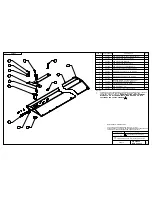
Step 2: Attach Fan Assembly to Mounting Hardware 

-


Reference: Page 12, View A of the High-5 Installation Instructions


A)


Using a scissor lift, raise the fan assembly until its mounting holes line up with the holes 
on the swivel joint at the bottom of the mounting hardware (see page 12, view A).  If a 
downrod is used, attach the fan assembly to the holes provided on the end of the rod.


B)


Important: 

Please note that the swivel joint (or downrod) must be located in between 

the mounting holes on the fan assembly.  Refer to page 12, View A.


C)


Secure the fan assembly to the mounting hardware (or end of the downrod) as shown 
on page 12 view A of the Installation Instructions.  


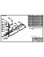
Step 3: Install Fan Assembly Safety Cable


-


Reference: Page 12, View A of the High-5 Installation Instructions


Note: This step is mandatory.  Failure to install the safety cable may void the manufacturer’s 
warranty. 


A)


  Pass one end of the safety cable through the holes on the assembly’s vertical supports 
(see page 12, view A).


Summary of Contents for HIGH-5

Page 1: ...HIGH 5 High Volume Ceiling Fan Installation Manual Blythewood SC 29016 800 768 3985 www pattersonfan com...

Page 2: ...ev 3 Page 4 Addendum To High 5 Installation Instructions Mechanical Only Please Note This document is meant to be used in conjunction with the Installation Instruction drawings that accompany this uni...

Page 3: ...oid the manufacturer s warranty FAN SPACING PLACEMENT AND CLEARANCE Fans should be mounted such that the blades are a minimum of 10 feet above the floor Also ensure that the fan blades have a clearanc...

Page 4: ...re proper lubrication Grease type is Mobil Unirex EP2 Add grease as needed filling slowly until grease passes through the upper seal hole Mounting Hardware All nuts and bolts related to mounting of th...

Page 5: ...rdware using the downrod clamp see page 11 of the Installation Instructions Step 2 Attach Fan Assembly to Mounting Hardware Reference Page 12 View A of the High 5 Installation Instructions A Using a s...

Page 6: ...nstall the guy wires may void the manufacturer s warranty The following steps should be performed with the aid of a scissor lift A Open the quick link located on the fan assembly Slide one eye of the...

Page 7: ...ll the way C Pitch the leading edge of the blade up Insert the 5 16 18 NC x 1 bolt with necessary washers through the fan hub and into the corresponding hole in the fan blade Tighten and secure this b...

Page 8: ...ternately through the holes at the corners of the fan hub pentagon and the holes of the blade pins see page 12 view C B Overlap the wire and clamp it together using 3 saddle clamps in the manner shown...

Page 9: ...BEFORE INSTALLING THE FAN ENSURE THAT THE STRUCTURE WHERE IT WILL BE FIXED IS SOLID ENOUGH TO SUPPORT THE LIVE LOAD OF IT SEE SPECIFICATIONS SHEET SECURE THE PRE ASSEMBLED INSTALLATION SUPPORT TO THE...

Page 10: ...IEW B 169735 202837 VIEW A 165710 4x INSTALLATION OF THE FRAME SAFETY CABLE 202164 THE WIRE ROPE PASSES OVER THE H BEAM AND THRU THE HOLES IN THE VERTICAL TUBES SADDLE CLIPS 187108 SHOULD BE INSTALLED...

Page 11: ...ASSY SET 202359 FAN HVLS 18 BLADE ASSY SET 202360 5 201988 FAN HVLS 5 8 11X3 1 2 BLADE BOLT 5 200153 BELLEVILLE SPRING LOCK WASHER 5 8 5 203135 HEX BOLT 5 16 18 NC X 1 LG Z P GR 5 10 201972 HEX BOLT 5...

Page 12: ...48510 FAN HVLS UPPER HUB BEARING CUP 1 13 163017 163016 25580 FAN HVLS BOTTOM HUB BEARING 25520 FAN HVLS BOTTOM HUB BEARING CUP 1 14 195376 FAN HVLS MAIN FRAME HUB H 618 GREASE FITTING BEARING CUPS IN...

Page 13: ...FOR COUPLING 1 18 145482 5016 WITH TWO SEALS COVER 1 19 110104 1 4 SQUARE KEY X 1 1 2 LG 2 20 203207 FAN HVLS 1 3 8 12 SLOTTED NUT MODIFIED 1 21 201896 FAN HVLS BLADES HUB WELDMENT 1 22 201972 HEX BO...

Page 14: ...MOVE FREELY ITEM NO PART NUMBER DESCRIPTION QTY 1 201845 FAN HVLS INST SUPPORT WELDMENT 1 2 201836 FAN HVLS INST SUPPORT TUBE ON CROSS MEMBER 1 3 202047 FAN HVLS INST SUPPORT BEAM SHIM 2 4 201839 FAN...

Page 15: ...1 4 SADDLE CLIP ZINC PLATED 4 8 201971 HEX BOLT 3 8 16 NC X 4 1 4 LG Z P GR 5 2 9 203412 WASHER 3 8 GR 8 13 32X13 16X 05 08 4 10 110665 NYLON INSERT LOCKNUT 3 8 16 Z P GR 5 2 11 169735 1 4 EYE EYE TUR...

Page 16: ...ALL OLD FASTENERS FOR SAFETY PURPOSE 3 ITEM NO PART NUMBER DESCRIPTION QTY 1 201895 FAN HVLS BLADE 24 ASSY WITH WINGLET 1 2 201863 FAN HVLS BLADE SHAFT SUPPORT 1 3 201965 FAN HVLS BLADE WINGLET SPARE...

Page 17: ...HVLS BLADE SAFETY PLATE 1 5 201988 FAN HVLS 5 8 11X3 1 2 BLADE BOLT 1 6 200153 BELLEVILLE SPRING LOCK WASHER 5 8 1 7 202674 HEX BOLT 5 16 18 NC X 1 2 LG Z P GR5 1 8 201972 HEX BOLT 5 16 18 NC X 3 4 LG...

Page 18: ...D ALL OLD FASTENERS FOR SAFETY PURPOSE 3 ITEM NO PART NUMBER DESCRIPTION QTY 1 202294 FAN HVLS BLADE 18 ASSY WITH WINGLET 1 2 201863 FAN HVLS BLADE SHAFT SUPPORT 1 3 201965 FAN HVLS BLADE WINGLET SPAR...

Reviews: