background image

pattersonfan.com

800.768.3985

19

STEP 4 - MOUNT THE REMOTE KEYPAD & CONNECT TO THE VFD


CAUTION:  It is vitally important that the remote keypad is ALWAYS mounted outside the blade 

radius of the fan.  This is especially important for the daisy chaining configuration (see page 25).  The 

daisy chaining process requires access to the keypad while the fan is in motion.

1) 

Once a desired location is found, affix 

the remote keypad to the wall using 

the mounting pads attached to the 

keypad enclosure. 

2)  Run the Cat 6 cable up to the 

fan-mounted VFD via the shortest 

possible path.  If possible, avoid 

lighting and other noise-producing 

electrical equipment.  Running the 

cable inside conduit is optional.

3) 

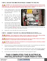
Pass the Cat 6 cable through the strain 

relief and then into the bottom of the 

drive.  Connect to the cable coupler 

and secure to the inside of the drive as 

shown in Image 19.  

DO NOT


connect the cable directly to the receptacle on the face of the VFD.  Be 

sure to tighten the strain relief on the bottom of the VFD.

4) 

Replace the cover of the VFD and screw down securely.

STEP 5 - CONNECT THE VFD TO A FIRE SUPPRESSION SYSTEM 

(OPTIONAL)


    WARNING:  There should be no voltage on the fire suppression system cable.  Placing voltage 

on the VFD terminal block will destroy the unit and void all manufacturers’ warranties.


    CAUTION:  DO NOT connect Patterson High-5 fans to the fans of another company for purposes 

of fire suppression.  A separate line must be run for Patterson fans ONLY.


   CAUTION:  If the drive will not be connected to any fire suppression system, the factory installed 

jumper across 9 & 15 MUST remain in place.

1) 

Remove the factory installed jumper between terminals 9 and 15.  The terminal block is located at the 

bottom of the ACS355.  For more information, refer to Image 18 on page 18.

2) 

Connect the fire suppression system wires to terminals 9 and 15.  Again, the fire system cable will 

leave the drive enclosure out of one of the holes on the bottom, using a strain relief

 (not provided)

.

3) 

Drive is now wired to shut down upon activation of any fire suppression signal.

THIS COMPLETES THE ELECTRICAL

INSTALLATION OF YOUR HIGH-5 FAN.

Cord Strain

Relief

Cable Coupler

IMAGE 19

Summary of Contents for HIGH-5

Page 1: ...HIGH 5 INSTALLATION INSTRUCTIONS For an electronic copy of these instructions please visit www pattersonfan com installation services and guides 208 230 460V Three Phase Input using ABB ACS355 VFD...

Page 2: ...ww pattersonfan com TABLE OF CONTENTS Safety Information Parts List Fan Placement Spacing and Clearance Fan Maintenance PART 1 Installation Instructions Mechanical PART 2 Installation Instructions Ele...

Page 3: ...o persons Patterson High 5s must be installed with Patterson High 5 supplied controllers that are marked on their cartons to indicate the suitability with this model Other controllers cannot be substi...

Page 4: ...e crimps for motor control cable d One 1 Cat 6 cable strain relief e One 1 Remote control keypad box f One 1 ACS355 drive User s Manual g One 1 ACS355 drive Supplement Manual h One 1 motor control cab...

Page 5: ...ean heat dissipating fins on the back of the box periodically Gearbox Periodic maintenance will ensure your fan remains operational for its intended life While Patterson recommends the end user check...

Page 6: ...pattersonfan com 800 768 3985 6 PART 1 MECHANICAL INSTALLATION...

Page 7: ...t level the mounting bracket can be mounted in either direction to allow the fan to swivel and hang straight 2 Refer to Image 1 to determine which set of bolt slots to use a For I beam width less than...

Page 8: ...k steel plate as shown in the diagram labeled Image 4 Consult a structural engineer for spanning distances greater than eight feet 2 Secure the spanning material to the building structure using bolts...

Page 9: ...f spanning structure thickness is greater than use provided spacer as shown in Image 6 5 If a down rod was ordered adjust the mounting bracket connectors to their widest position Refer to Image 6 6 At...

Page 10: ...AN 1 Using the hardware packet provided attach the VFD to the side of the frame with the VFD brackets A properly installed VFD is shown in Image 9 I beam mount or Image 10 mount with spanning structur...

Page 11: ...efer to Images 9 and 10 for more information 2 The opposite end of the safety cable should be passed over the top of the I beam or other mounting structure Connect the two ends of the cable together b...

Page 12: ...cable making sure the fan assembly remains in the vertical position Use 3 saddle clamps to crimp the end of the guy wire together Image 14 Ensure saddle clamps are positioned so that the teeth on the...

Page 13: ...the fan blade into position until all blade bolt holes on the fan blade and safety bracket are aligned Replace blade bolts nuts and washers Torque to 65 ft lbs 3 Install blade flaps using bolts and en...

Page 14: ...box seals to leak due to pressurization of the lubrication fluid possibly voiding the manufacturer s warranty 1 Remove plug in the gearbox and replace with vent prior to operation of the fan The vent...

Page 15: ...tersonfan com 800 768 3985 15 WARNING This portion of the installation MUST be completed by a licensed electrician with knowledge of all national and local electrical codes PART 2 ELECTRICAL INSTALLAT...

Page 16: ...ions contact the manufacturer WARNING Before servicing or cleaning unit switch power off at service panel and lock the service disconnecting means to prevent power from being switched on accidentally...

Page 17: ...appropriately sized knockout 3 Connect conductors to terminals L1 L2 and L3 respectively Ground wire should be fastened to the protective earth PE 4 Continue running input power to the drive by connec...

Page 18: ...secured by the cable clamp as shown in Image 18 4 Connect the opposite end of the motor control cable to the fan motor This will require removal of one of the knockouts on the motor s junction box As...

Page 19: ...on the bottom of the VFD 4 Replace the cover of the VFD and screw down securely STEP 5 CONNECT THE VFD TO A FIRE SUPPRESSION SYSTEM OPTIONAL WARNING There should be no voltage on the fire suppression...

Page 20: ...800 768 3985 20 WARNING Please read carefully and completely before beginning the daisy chaining procedure PART 3 DAISY CHAINING This section is optional and is not necessary to complete the installa...

Page 21: ...the fans downstream will begin to rotate at the speed of that fan NOT the designated master Each follower must be wired according to the diagram below The VFD designated as the master will be wired i...

Page 22: ...ecessary However if the speed is slower than the master go to Step b b Unlock the follower s parameter set i Set the fan in local mode by pressing the LOC REM button ii Press the MENU key on the keypa...

Page 23: ...re lock each fan s parameter set after adjusting the speed scale reversing the instructions in Step b This will prevent unnecessary tampering with fan drive parameters e Once all followers have been p...

Reviews: