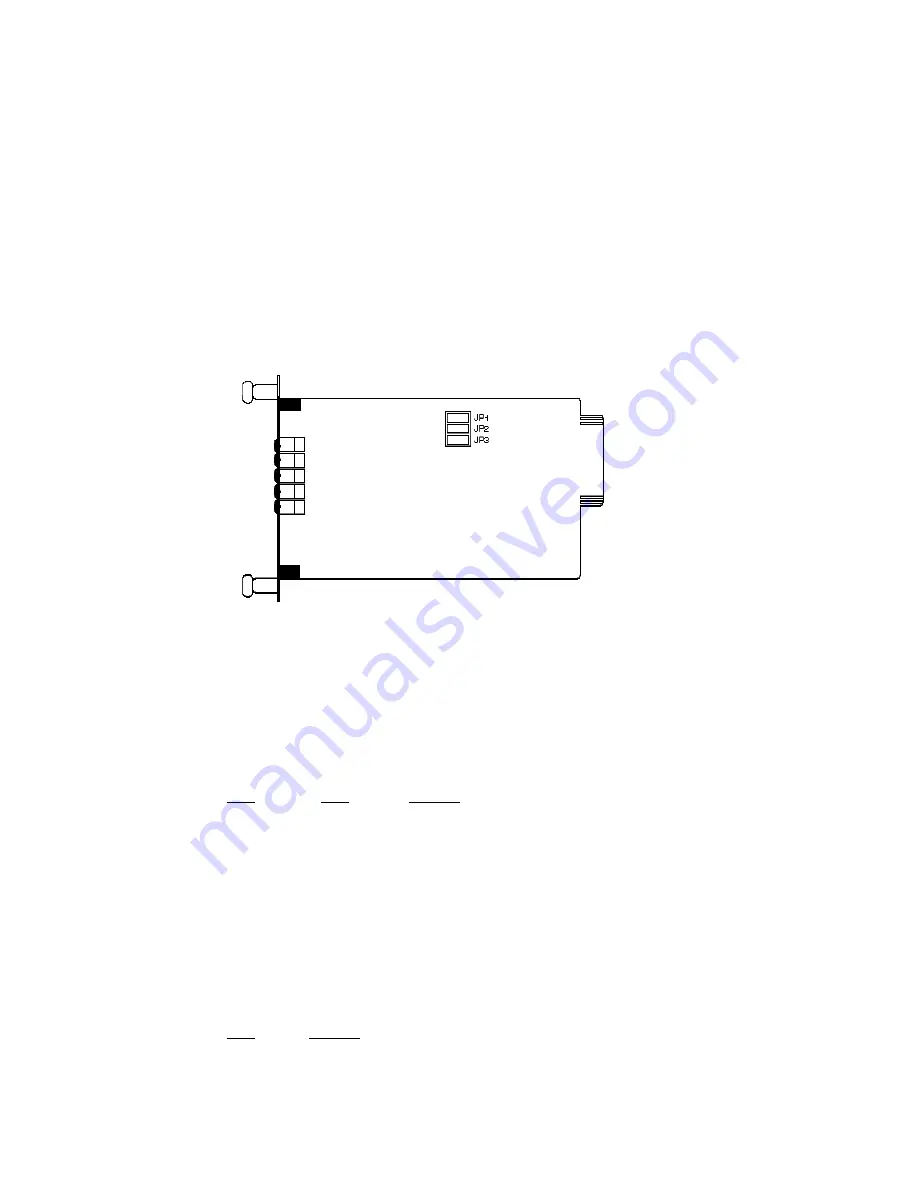
3.0 CONFIGURATION
This setting describes the location and orientation of the Model
1110ARC’s configuration jumpers. There are two sets of jumpers to
set: those on the front “brains” card and those on the rear “interface”
card.
3.1 FRONT CARD SETTINGS
The jumpers on the Model 1110ARC “brains” card set RTS/CTS
delay and carrier control. Figure 1 (below) shows their location on the
PC board.
JP1 and JP2: RTS/CTS Delay
The combined settings for jumpers JP1 and JP2 determine the
amount of delay between the time the Model 1110ARC “sees” RTS and
when it sends CTS.
JP1
JP2
Setting
Off
Off
No delay
On
Off
No delay
On
On
9.0 mS
Off
On
79.5 mS
JP3: Carrier Detect
The settings for jumper JP3 determines whether carrier detect is
enabled or disabled. Carrier detect feature responds to RTS; if RTS is
on, the Model 1110ARC will have a carrier.
JP3
Setting
On
Enabled
Off
Disabled
2.0 GENERAL INFORMATION
Thank you for your purchase of this Patton Electronics product.
This product has been thoroughly inspected and tested and is
warranted for One Year parts and labor. If any questions during
installation or use of the 1110ARC, contact Patton Electronics Technical
Support at (301) 975-1007.
2.1 FEATURES
• Communicates over dual optical fibers
• RS-232 Data rates to 19.2 Kbps
• Distances to 4 miles
• Mounts in Patton’s 16-Card Rack Chassis
• Compatible with the Patton Model 1110A self-powered modem
• Immune to RFI/EMI noise, ground loops and transient surges
• Easily accessible configuration jumpers
• Bi-level LED status indicators
• Works with switchable 120V or 240V rack mount power supply
• SMA or ST connectors available (HD-26 female RS-232 port)
2.2 DESCRIPTION
The Patton Model 1110ARC fiber optic rack card modem
is the
rack mountable counterpart to Patton’s Model 1110A self-powered, fiber
optic modem. Communicating full or half duplex over dual optical
fibers, the Model 1110ARC supports data rates to 19.2 Kbps and
distances to 4 miles.
Like all fiber optic modems, the Model 1110ARC is inherently
immune to RFI/EMI noise, ground loops and transient surges. The
carrier may be switch selected as either “Continuously On” or
“Controlled by RTS”. Four pairs of bi-level LED indicators monitor TD,
RD, RTS and CD. A single LED monitors power.
The Model 1110ARC is designed to mount in Patton’s 2U high 19”
rack chassis. This 16-card chassis has a switchable 120/240 volt
power supply and mounts cards in a mid-plane architecture: The front
“brains” half-card can be plugged into different rear “interface” cards.
The Model 1110ARC is available with a choice of two interface cards:
one with SMA connectors, and one with ST connectors. Both cards are
equipped with an HD-26 female connector for the RS-232 interface.
3
4
Figure 1.
Model 1110ARC front card jumper locations


