


2
OnSite Expansion Modules Quick Start Guide
1.0 Introduction
This guide provides instructions for adding expansion modules to your Patton OnSite base system. Refer to the
following sections for installation instructions for your specific module:
•
2.0 “Model 9100 E1 Module”
on page 2
•
3.0 “Model 9130 DS3/E3 Module”
on page 4
•
4.0 “Model 9200 Ethernet Module”
on page 5
•
5.0 “Model 9300 STM-1 Module”
on page 6
2.0 Model 9100 E1 Module
2.1 Unpacking and Installation
To install the HD-E1 module, follow the procedures in Chapter 7 of the
OnSite Series Administrator’s Reference
Guide
.
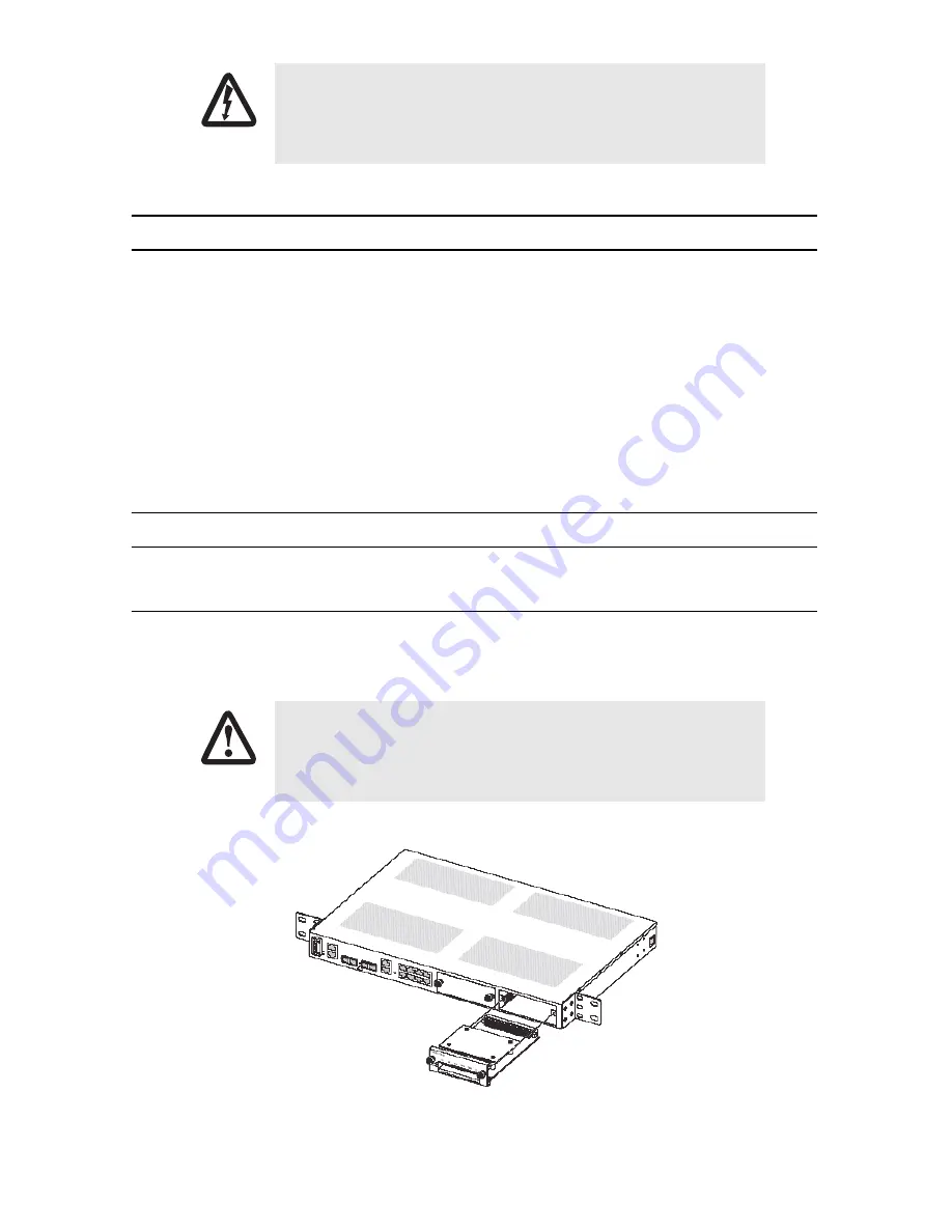
Figure 1
shows the alignment and insertion of the HD-E1 module into one of the available expansion
slots of the OS-10.
Figure 1.
Installing the HD-E1 module
Read the safety information in the OnSite Series
User Manual
and
Administrator’s Reference Guide
thoroughly before installing and operat-
ing your OS-10 Series system. Failure to follow this safety information
can lead to personal injury or damage to the equipment.
The High-density E1 module is NOT hot swappable. You will need to
power down the OS-10 system before starting the module insertion pro-
cedure.
WARNING
CAUTION


