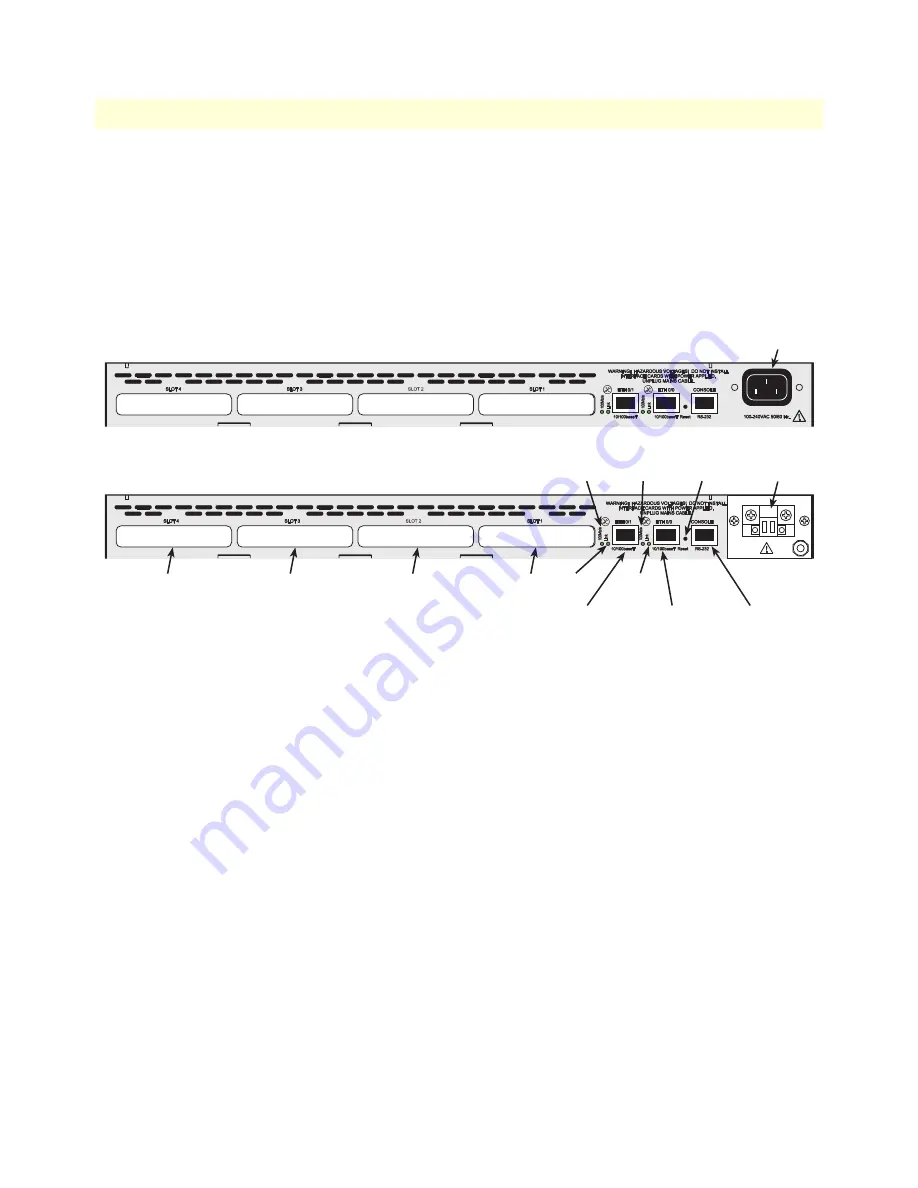
SmartNode 2400 description
31
SmartNode 1000 and 2000 Series Getting Started Guide
1 • General Information
Rear panel
The SmartNode 2400 rear panel is depicted in
figure 13
. There are four expansion slots for optional interface
cards, and four board-mounted sockets. There are four expansion slots for optional interface cards, and four
board-mounted sockets. The Link, and 100Mb/s LEDs indicate the status of the Ethernet ports. See
appendix C,
“Cabling”
on page 142 for connection cable and appendix D,
“Port pin-outs”
on page 150 for
pin-out data.
Figure 13. SmartNode 2400 rear panel
Expansion slots
The slots labeled SLOT 1, SLOT 2, SLOT 3 and SLOT 4 (see
figure 13
) accept different PMC interface cards
to integrate voice and data over IP networks (see section
“Interface cards descriptions”
on page 33 for
more information).
On-board ports
Three motherboard-mounted network interfaces are available for use, independent of those that may be
included with interface cards mounted in SLOT 1, SLOT 2, SLOT 3, or SLOT 4. The motherboard-mounted
100–240 VAC
50/60 Hz
power connector
36–72 VDC
1 Amp
Terminal block
AC power version
DC power version
(Model SN2400/48 only)
SLOT
4
SLOT
3
SLOT
2
SLOT
1
ETH 0/1
10/100Base-T port
ETH 0/0
10/100Base-T port
CONSOLE
RS-232 port
Link
LED
Link
LED
Reset
button
100Mb/s
LED
100Mb/s
LED


