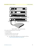
Installing the SmartNode device
33
SmartNode 5540 & 4140 Series User Manual
3
• SmartNode Installation
Connecting the 10/100/1000Base-T Ethernet LAN and WAN cables
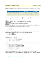
The SmartNode device has automatic MDX (auto-cross-over) detection and configuration on the Ethernet
ports. Any of the two ports can be connected to a host or hub/switch with a straight-through wired cable.
1.
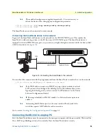
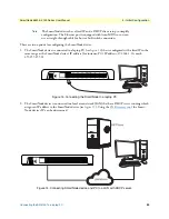
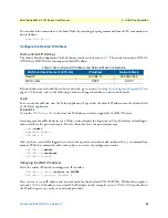
Connect to the subscriber port of the broadband access modem (DSL, cable, WLL) to ETH 0/0.
2.
Connect port ETH 0/1 to your LAN.
3.
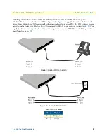
If your SmartNode device is equipped with an xDSL WAN interface, refer to section Connecting the
xDSL WAN interface cables
For details on the Ethernet port pinout and cables, refer to Appendix
on page 54 and
Appendix
Refer to Appendix
on page 58 for port pinouts of the DSL interfaces
Installation cable requirements for the DSL & Fiber WAN cable (SN5540/2G, /4G, /AVA, /AVB, /F
Models)
The SmartNode Model SN5540 comes with an optional Fiber-SFP, G.SHDSL(EFM-ATM) or VDSL-ADSL
WAN interface. Use a straight-through RJ-45 cable to connect the DSL port or a fiber optic cable to connect to
the SFP port
For details on the G.SHDSL port pinout, refer to section
“G.SHDSL EFM & ATM port (/2G and /4G mod-
For details on the VDSL and ADSL port pinout, refer to section
“VDSL-ADSL Port (/A and /AVA & /AVB
For details on the Fiber connection, refer to section
“Fiber Ports (/F models only)”
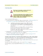
Connecting the power supply
Do the following to connect the main power to the SmartNode device:
1.
Verify that the AC power supply included with your device is compatible with local standards. If it is not,
refer to Chapter 5,
“Contacting Patton for Assistance”
on page 42 to find out how to replace it with a com-
patible power supply.
Note
The SmartNode does not have a power switch; it powers on when the device
is plugged in.
2.
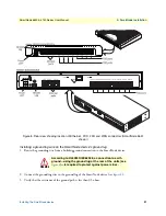
The power connection is made via the barrel jack on the rear panel of the SmartNode. No configuration is
necessary for the power supply.
Connect the female end (barrel plug) to the barrel jack on the rear of the SmartNode (see
on page 19 for an SN4140) and the power supply male connectors to
an appropriate power outlet.
3.
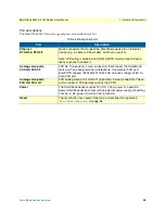
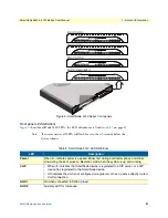
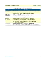
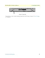
Verify that the green
Power
on page 34). It blinks fast during bootloader phase and
blinks slow during boot process of Trinity Software. It becomes solid when the system is up and running.

