background image

SmartNode 10100 Series Quick Start Guide

5

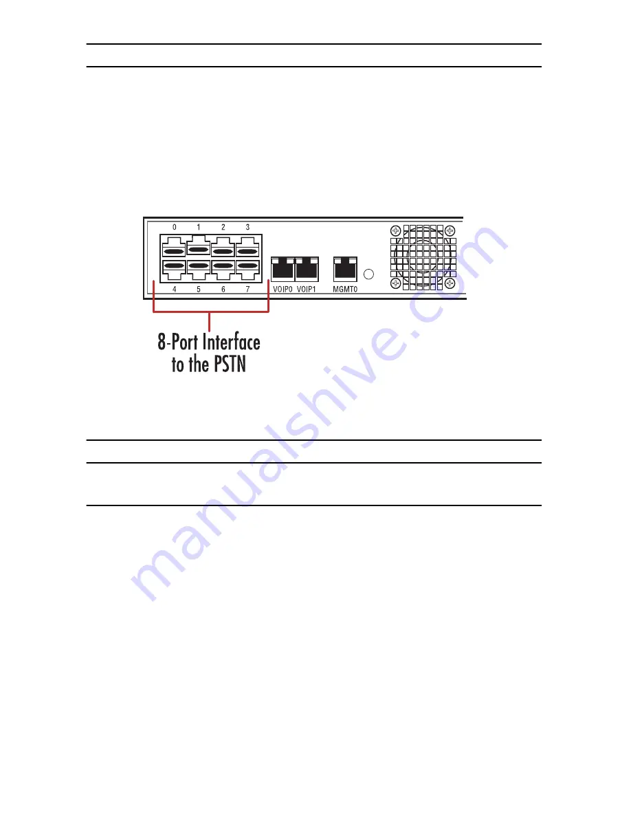
4.0  Connecting to the PSTN Network

A SN10100 with 8 RJ48C type ports enables the connection to T1/E1 lines.

Note

T1/E1 ports are activated by software license; the number of active ports 

depends on the licenses purchased.

   1.

Start with port 0, located at the top and leftmost position. Connect one cable between this port and the 
T1/E1 line.

   2.

Repeat step 1, using the next available port.

Figure 3. 

Port Interface to the PSTN

5.0  Connecting to the Power source

5.1  AC Power

The SN10100 connects to two independent power sources. If only one power source is used, press the green but-
ton at the rear of the unit to disable the audible alarm.

   1.

Connect an AC power cable between the AC connector of the SN10100 and an AC supply.

Summary of Contents for SmartNode 10100 Series

Page 1: ...ck Start Guide This is a Class A device and is not intended for use in a residential environment Part Number 07MSN10100 QS Rev A Revised April 9 2014 Sales Office 1 301 975 1000 Technical Support 1 30...

Page 2: ...C powered devices ensure that the interconnecting cables are rated for proper voltage current anticipated temperature flammabil ity and mechanical serviceability WAN LAN PSTN ports connections may hav...

Page 3: ...le are included with DC units Electrostatic Discharge ESD can damage equipment and impair electrical circuitry It occurs when electronic printed circuit cards are improperly handled and can result in...

Page 4: ...of the SN10100 Connect the other end of the same CAT5 cable to the Gigabit Ethernet switch 2 If your system employs a second Gigabit Ethernet switch for redundancy connect a second CAT5 Ethernet cable...

Page 5: ...t 0 located at the top and leftmost position Connect one cable between this port and the T1 E1 line 2 Repeat step 1 using the next available port Figure 3 Port Interface to the PSTN 5 0 Connecting to...

Page 6: ...er connection ports and is supplied with two DC power cables 1 Connect one DC cable to the DC outlet at the rear of the SN10100 2 Connect one lead of the DC power cable to the positive terminal of the...

Page 7: ...shipment 3 Refer to the Important Notice sheet for the username and password to log onto the Control host Navi gate to HTTP HOSTNAME 12358 to configure the SmartNode unit username password root root...

Page 8: ...via the Console Serial port Logging into the SmartNode Console 1 To physically connect the Consol Serial port follow the instructions in section 6 1 Connecting the Console Serial port on page 7 2 To...

Page 9: ...cated tasks like advanced debugging For debugging assistance contact Patton s Support team at support patton com Once your IP Address and Time Zone are set there are no more configuration steps in the...

Page 10: ...t installed and used properly that is in strict accordance with the manufacturer s instructions may cause interference to radio and television reception This equipment has been tested and found to com...

Page 11: ...ective is indicated by CE mark on the device A 4 Authorized European Representative D R M Green European Compliance Services Limited Avalon House Marcham Road Abingdon Oxon OX14 1UD UK B 0 Customer an...

Page 12: ...s no liability for errors that may appear in this document Trademarks statement The term SmartNode is a trademark of Patton Electronics Company All other trademarks presented in this docu ment are the...

Reviews: