Installing the SmartNode device
31
SmartNode 5541 & 4141 Series User Manual
3
• SmartNode Installation
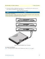
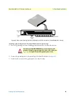
Installing an interface cable on the SmartNode device’s FXS interface ports
The SmartNode comes with at least two FXS analog ports (see
on page 30) located on the back of the
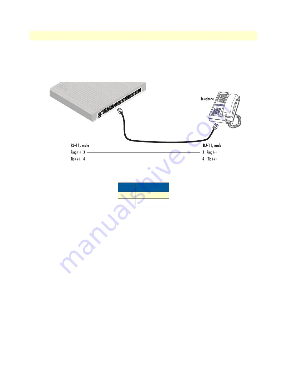
device. The FXS interfaces are connected to analog devices via cables (see
) terminated with RJ-11 connec-
for pin-out information).
Figure 9. Analog FXS connection
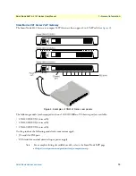
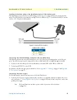
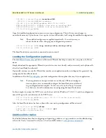
Connecting the 10/100/1000Base-T Ethernet LAN and WAN cables
The SmartNode device has automatic MDX (auto-cross-over) detection and configuration on the Ethernet
ports. Any of the two ports can be connected to a host or hub/switch with a straight-through wired cable.
1.
Connect to the subscriber port of the broadband access modem (DSL, cable, WLL) to ETH 0/0.
2.
Connect port ETH 0/1 to your LAN.
For details on the Ethernet port pinout and cables, refer to
Appendix C, “Cabling”
on page 49 and
Appendix
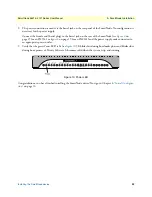
Connecting the power supply
Do the following to connect the main power to the SmartNode device:
1.
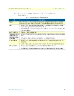
Verify that the AC power supply included with your device is compatible with local standards. If it is not,
refer to Chapter 5,
“Contacting Patton for Assistance”
on page 40 to find out how to replace it with a com-
patible power supply.
Note
The SmartNode does not have a power switch; it powers on when the device
is plugged in.
Table 9. RJ-11 socket
Pin
Signal
3
Ring (-)
4
Tip (+)

