background image

FCC Part 68 (ACTA) Statement

39

SmartNode 5480 & 5490 User Manual 

A

 •

Compliance Information

FCC Part 68 (ACTA) Statement 

This equipment complies with Part 68 of FCC rules and the requirements adopted by ACTA. On the bottom 
side of this equipment is a label that contains—among other information—a product identifier in the format 
US: AAAEQ##TXXXX. If requested, this number must be provided to the telephone company.

The method used to connect this equipment to the premises wiring and telephone network must comply with 
the applicable FCC Part 68 rules and requirements adopted by the ACTA.

If this equipment causes harm to the telephone network, the telephone company will notify you in advance 
that temporary discontinuance of service may be required. But if advance notice isn’t practical, the telephone 
company will notify the customer as soon as possible. Also, you will be advised of your right to file a complaint 
with the FCC if you believe it is necessary.

The telephone company may make changes in its facilities, equipment, operations or procedures that could 
affect the operation of the equipment. If this happens the telephone company will provide advance notice in 
order for you to make necessary modifications to maintain uninterrupted service.

If trouble is experienced with this equipment, for repair or warranty information, please contact our company. 
If the equipment is causing harm to the telephone network, the telephone company may request that you dis-
connect the equipment until the problem is resolved.

Connection to party line service is subject to state tariffs. Contact the state public utility commission, public 
service commission or corporation commission for information.

Industry Canada Notice 

This equipment meets the applicable Industry Canada Terminal Equipment Technical Specifications. This is 
confirmed by the registration number. The abbreviation, IC, before the registration number signifies that regis-
tration was performed based on a Declaration of Conformity indicating that Industry Canada technical speci- 
fications were met. It does not imply that Industry Canada approved the equipment.

This Declaration of Conformity means that the equipment meets certain telecommunications network protec-
tive, operational and safety requirements. The Department does not guarantee the equipment will operate to 
the user's satisfaction. Before installing this equipment, users should ensure that it is permissible to be con-
nected to the facilities of the local telecommunications company. The equipment must also be installed using 
an acceptable method of connection. In some cases, the company’s inside wiring associated with a single line 
individual service may be extended by means of a certified connector assembly (telephone extension cord). The 
customer should be aware that compliance with the above condition may not prevent degradation of service in 
some situations. Repairs to some certified equipment should be made by an authorized maintenance facility 
designated by the supplier. Any repairs or alterations made by the user to this equipment, or equipment mal-
functions, may give the telecommunications company cause to request the user to disconnect the equipment. 
Users should ensure for their own protection that the ground connections of the power utility, telephone lines 
and internal metallic water pipe system, are connected together. This protection may be particularly important 
in rural areas.

Summary of Contents for SmartNode 5480 Series

Page 1: ...07 E mail support patton com WWW www patton com Part Number 07MSN5480 90 UM Rev A Revised May 29 2013 Important This is a Class A device and is not intended for use in a residential environment If a c...

Page 2: ...document is furnished under a license and may be used or copied only in accordance with the terms of such license For information about the license see Appendix F End User License Agreement on page 56...

Page 3: ...rview 22 3 SmartNode Installation 24 4 Initial Configuration 29 5 Contacting Patton for Assistance 34 A Compliance Information 37 B Specifications 41 C Cabling 46 D Port Pin outs 49 E SmartNode 5480 a...

Page 4: ...ar Panels 16 SmartNode 5480 Rear Panel 16 SmartNode 5490 Rear Panel 17 SmartNode 5480 and 5490 Series Front Panels 19 SmartNode 5480 Front Panel 19 SmartNode 5490 Front Panel 20 2 Applications Overvie...

Page 5: ...4 Introduction 35 Contact Information 35 Patton support headquarters in the USA 35 Alternate Patton support for Europe Middle East and Africa EMEA 35 Warranty Service and Returned Merchandise Authoriz...

Page 6: ...7 Ethernet 48 D Port Pin outs 49 Introduction 50 Console Port 50 Ethernet 50 G SHDSL Port 51 EFM Port 52 Fiber Port 52 E SmartNode 5480 and 5490 Series Factory Configuration 53 Introduction 54 F End U...

Page 7: ...cation 23 7 SN5490 typical application 23 8 SN5480 5490 rear panel 28 9 SN5480 5490 Power LED 28 10 Connecting the SmartNode to your laptop PC 30 11 Connecting the SmartNode to the network 32 12 Conne...

Page 8: ...17 6 SN5480 Front panel LEDs 19 7 SN5490 Front panel LEDs 21 8 Sample site log entries 25 9 Factory default IP address and network mask configuration 31 10 G SHDSL Daughter Card Specifications 44 11 S...

Page 9: ...age 24 provides hardware installation procedures Chapter 4 on page 29 provides quick start procedures for configuring the SmartNode Chapter 5 on page 34 contains information on contacting Patton techn...

Page 10: ...g calls attention to important information The alert symbol and CAUTION heading indicate a potential haz ard Strictly follow the instructions to avoid property damage The shock hazard symbol and CAUTI...

Page 11: ...es are rated for proper voltage current anticipated temperature flammability and mechanical serviceability WAN LAN PSTN ports connections may have hazardous voltages present regardless of whether the...

Page 12: ...ates a cross reference hyperlink that points to a figure graphic table or sec tion heading Clicking on the hyperlink jumps you to the reference When you have finished reviewing the reference click on...

Page 13: ...erview 14 SN5480 Series Model Codes 15 SN5490 Series Model Codes 15 CodesSmartNode 5480 and 5490 Series Rear Panels 16 SmartNode 5480 Rear Panel 16 SmartNode 5490 Rear Panel 17 SmartNode 5480 and 5490...

Page 14: ...SP creating a single conduit for multimedia compo nents including voice video and data Figure 1 SmartNode 5480 left and SmartNode 5490 right The SmartNode 5480 and 5490 Series Enterprise Session Borde...

Page 15: ...r in the number of transcoding sessions they can support and G SHDSL X 21 EFM or Fiber SFP options All models come equipped with two 10 100 1000 Base T Ethernet ports Table 2 SmartNode 5480 Models Mod...

Page 16: ...aintenance the Console port see Figure 2 an RS 232 RJ 45 connector connects the product to a serial terminal such as a PC or ASCII terminal also called a dumb terminal 12V DC 1 0A Electricity supply s...

Page 17: ...le 5 SN 5490 rear panel ports Port Description WAN ETH 0 0 Auto MDX Gigabit Ethernet port RJ 45 see Figure 2 connects the unit to an Ethernet WAN device for example a cable modem DSL modem or fiber mo...

Page 18: ...orts which are still DOWN 1 BLINK Pair 1 2 BLINKS Pair 2 3 BLINKS Pair 3 4 BLINKS Pair 4 Console Used for service and maintenance the Console port see Figure 2 an RS 232 RJ 45 connector connects the p...

Page 19: ...ure 4 shows SmartNode 5480 Series front panel LEDs the LED definitions are listed in Table 6 Figure 4 SmartNode 5480 Series front panel Table 6 SN5480 Front panel LEDs LED Description 1ote If an error...

Page 20: ...figured or registered or has no active direct routed VoIP connection Flashing green indicates that the unit is attempting to register or has failed to register Ethernet Link On when the Ethernet conne...

Page 21: ...ed VoIP connection Flashing green indicates that the unit is attempting to register or has failed to register Ethernet Link On when the Ethernet connection on the corresponding port has a link indicat...

Page 22: ...22 Chapter 2 Applications Overview Chapter contents Introduction 23 Typical Application 23...

Page 23: ...ations can be found online at www patton com smartnode Typical Application The SN5480 5490 enables Universal SIP Trunking and provides a single Integrated Access Device with fea tures like IP Routing...

Page 24: ...are Tools 26 AC Power Mains 26 Location and Mounting Requirements 26 Installing the SmartNode 26 Placing the SmartNode 26 Installing Cables 26 Connecting the 10 100 1000Base T Ethernet LAN and WAN cab...

Page 25: ...clude information such as listed in Table 8 Network Information Network connection considerations that you should take into account for planning are provided for several types of network interfaces ar...

Page 26: ...Node is intended to be placed on a desktop or similar sturdy flat surface that offers easy access to the cables Allow sufficient space at the rear of the chassis for cable connections Additionally you...

Page 27: ...ode Ethernet ports operate in Full Duplex mode only Do not connect to Half Duplex ports For best results use auto negotiation Auto negotiation is mandatory when using 1000BaseT Gigabit Ethernet 2 Conn...

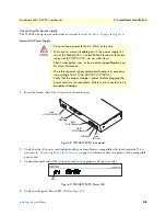
Page 28: ...the green Power LED is lit see Figure 9 Do not connect power to the AC Mains at this time There are no user serviceable parts in the power supply sec tion of the Model 5400 Contact Patton Electronics...

Page 29: ...Connecting the SmartNode to Your Laptop PC 30 2 Configuring the Desired IP Address 31 Factory default IP Settings 31 Login 31 Changing the WAN IP Address 31 3 Connecting the SmartNode to the Network...

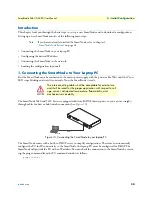
Page 30: ...eady The SmartNode 5480 and 5490 Series is equipped with Auto MDX Ethernet ports so you can use straight through cables for host or hub switch connections see Figure 10 Figure 10 Connecting the SmartN...

Page 31: ...default IP address for the SmartNode into the address field 192 168 1 1 Accessing your SmartNode via a Telnet session displays the login screen Type the factory default login administrator and leave t...

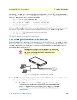
Page 32: ...SmartNode will connect to the network via the WAN ETH 0 0 port This enables the Smart Node to offer routing services to the PC hosts on LAN ETH 0 1 port The SmartNode 5480 and 5490 Series is equipped...

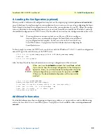
Page 33: ...SmartNode device In this example we assume the TFTP server on the host with the IP address 172 16 1 11 and the configuration named SN cfg in the root directory of the TFTP server 172 16 1 99 if ip WAN...

Page 34: ...n Support Headquarters in the USA 35 Alternate Patton Support for Europe Middle East and Africa EMEA 35 Warranty Service and Returned Merchandise Authorizations RMAs 35 Warranty Coverage 35 Out of war...

Page 35: ...x 1 301 869 9293 Alternate Patton Support for Europe Middle East and Africa EMEA Online support available at www patton inalp com E mail support e mail sent to support patton inalp com will be answere...

Page 36: ...l be issued upon receipt and inspection of the equipment 30 to 60 days We will add a 20 restocking charge crediting your account with 80 of the purchase price Over 60 days Products will be accepted fo...

Page 37: ...ompliance Information Chapter contents Compliance 38 EMC 38 Safety 38 PSTN Regulatory 38 FCC Part 68 ACTA Statement 39 Industry Canada Notice 39 CE Declaration of Conformity 40 Authorized European Rep...

Page 38: ...al A Compliance Information Compliance EMC EN55022 Class A EN55024 Safety IEC EN60950 1 2nd edition PSTN Regulatory ACTA Part 68 IC CS 03 AS ACIF S016 2001 AS ACIF S038 2001 ETSI TBR 12 TBR 12 A1 TBR...

Page 39: ...mmission public service commission or corporation commission for information Industry Canada Notice This equipment meets the applicable Industry Canada Terminal Equipment Technical Specifications This...

Page 40: ...C relating to electrical equipment designed for use within certain voltage limits and Directive 2011 65 EC relat ing to RoHS compliance The Declaration of Conformity may be obtained from Patton Electr...

Page 41: ...s Data Connectivity 42 Voice Processing signaling dependent 42 Fax and Modem Support 42 Voice Signaling 42 IP Services 43 Management 43 System 43 Physical 43 WAN Daughter Card if applicable 44 Identif...

Page 42: ...G 168 echo cancellation 128 ms Up to 120 simultaneous voice or T 38 fax calls DTMF detection and generation Carrier tone detection and generation Silence suppression and comfort noise Adaptive and con...

Page 43: ...based GUI Industry standard CLI with local console RJ 45 RJ 231 9600 bps 8 N 1 and remote Telnet access fully documented HTTP web management and firmware loading TFTP configuration firmware loading SN...

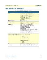
Page 44: ...t I 610 OAM F4 F5 Management interfaces GUI and Telnet Software upgrade GUI and TFTP ATM Support Classical IPoA RFC 1577 2225 PPPoE Client over ATM RFC 2516 IPoA RFC 2684 1483 ATM AAL5 encapsulation M...

Page 45: ...realized with the SmartNode product identification MIB Table 11 SmartNode Models and their Unique sysObjectID SmartNode Model SysObjectID SN5480 32P iso org dod internet private enterprises patton pr...

Page 46: ...46 Appendix C Cabling Chapter contents Introduction 47 Console 47 Ethernet 48...

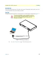
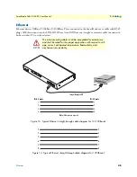
Page 47: ...as depicted in Figure 12 Figure 12 Connecting a serial terminal 1ote See section Console Port on page 50 for console port pin outs The interconnecting cables shall be acceptable for external use and s...

Page 48: ...hernet straight through cable diagram for 10 100Base T Figure 14 Typical Ethernet straight through cable diagram for 1000Base T The interconnecting cables shall be acceptable for external use and shal...

Page 49: ...49 Appendix D Port Pin outs Chapter contents Introduction 50 Console Port 50 Ethernet 50 G SHDSL Port 51 EFM Port 52 Fiber Port 52...

Page 50: ...iguration settings 9600 bps 8 bits no parity 1 stop bit no flow control Figure 15 EIA 561 RJ 45 8 pin port 1ote N C means no internal electrical connection Ethernet 1ote Pins not listed are not used T...

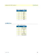
Page 51: ...Pin outs G SHDSL Port Table 13 RJ45 socket 1000Base T Pin Signal 1 TRD0 2 TRD0 3 TRD1 6 TRD1 4 TRD2 5 TRD2 7 TRD3 8 TRD3 Table 14 RJ 45 connector Pin Signal 1 No connection 2 No connection 3 Tip 2 4 T...

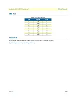
Page 52: ...EFM Port Fiber Port For tested and approved modules please refer to the list of SFP s Patton has tested at http www patton com products sfpmodules asp Table 15 RJ 45 connector Pin Signal Pair 1 Tip 1...

Page 53: ...53 Appendix E SmartNode 5480 and 5490 Series Factory Configuration Chapter contents Introduction 54...

Page 54: ...irect patton com system mac mac system mac serial system serial hwMajor system hw major hwMi nor system hw minor swMajor system sw major swMinor system sw minor swDate s ystem sw date productName syst...

Page 55: ...xt ip router interface WAN ipaddress dhcp use profile napt NAPT_WAN tcp adjust mss rx mtu tcp adjust mss tx mtu interface LAN ipaddress 192 168 1 1 255 255 255 0 tcp adjust mss rx mtu tcp adjust mss t...

Page 56: ...F End User License Agreement Chapter contents End User License Agreement 57 1 Definitions 57 2 Title 57 3 Term 57 4 Grant of License 57 5 Warranty 57 6 Termination 58 7 Other licenses 58 8 SmartWare...

Page 57: ...gnated Equipment at a site owned or leased by the End User B The End User may copy licensed Program s as necessary for backup purposes only for use with the Des ignated Equipment that was first purcha...

Page 58: ...Agreement should End User violate any of the provisions of section 4 Grant of License on page 57 C Upon termination for A or B above or the end of the Term End User is required to destroy all copies o...

Reviews: