background image


14

Hopper Front View 


Hopper Rear View 


Hopper Bottom View 


Feeder Top View 


5

8

6

7

10 

11 

12 

13 

14 

15 

17 

16 

18 

Item#   


Description 


Part # 


  Hopper 

Casting 

      545 


  Chamber 

Lid 

      545-A 

    3 


Hex Hold Down Bolt (also used as Hopper hold down)   

556B 

    4 


X-Bolt   


570 

    5 


Guard Post Guard Information Plate 


551-B 

    6 


Meat Stop c/w Washer   


555                     

    7 


Pressure Plate Block Hardware   


548-C   


  Pressure 

Plate 

Block 

     547 

    9 


Mold Plate Guard Post (2) 


551 

    10 


Mold Plate Guard Knob and Washer(2 Required) 


550-1 


11 

  Hopper 

Threaded 

Plug 

     607 


12 

  Guard 

Post 

Screw 

     551-A 


13 

  Hopper 

Nylon 

Bushing 

     603 

    14 


Hopper Nylon Bushing Set Screw(3 Required)   


604 


    15 


Feeder   


557 


16 


Mixer  Collar  Set  Screw   


559 

    17 


Mixer Collar 


558 

    18 


Witness Marks (one on Feeder and Mixer Collar for location) 

N/A


. . 

Summary of Contents for 330A

Page 1: ...od Machines Model 330A Owner s Manual Revised January 2011 Patty O Matic Inc Route 547 P O Box 404 Farmingdale NJ 07727 Tel 732 938 2757 Fax 732 938 5809 Toll Free in USA 877 938 5244 Website www patt...

Page 2: ...ion Feed Tray Assembly Page 13 Mold Plate Guard Assembly Page 13 Knock Out Cup Assembly Page 13 Hopper Assembly Page 14 Feeder Assembly Page 14 Assembled Machine Views Page 15 Paper Interleaver Assemb...

Page 3: ...old Plate Guard must be installed on the machine to engage the interlock on the front of the machine and the Feed Tray including the Guard must be installed on top of the Hopper to engage the interloc...

Page 4: ...Parts Box 655 Holds Spare Parts Patty Paper Sample Machine Lubricant Speed Driver and Locator Rings 2 Receiving Table 609 6 3 Speed Driver 544 4 Bottle of Machine Lubricant and Cleaner 600 5 Gallon o...

Page 5: ...e View Spacer Plate Mold Plate Assembly Side View T Knob Mold Plate Assembly Underside View Back Drive T Knob Hole Feed Tray Guard Feed Tray Guard and Mold Plate Guard are installed for your safety Do...

Page 6: ...6 Proper Label Location for a Model 330A 1 2 3 4 5 6 7 8 9 10 10 11 2 6 12...

Page 7: ...Orange 514 02 3 Patty O Matic 514 08 4 Safety instructions 514 06 5 Danger Label 1 514 03 6 Danger Label 2 514 00 7 Serial Tag 514 15 8 Store Tool 514 14 9 Warning Manual 514 01 10 Danger on off 514...

Page 8: ...ding machines It is nothing to be concerned with There are certain machine settings that may lessen this accumulation Setting the Ring Pin Pressure Plate for your Patty Size The Purpose of the Pressur...

Page 9: ...on the front right corner of the Mold Plate For example if your Mold Plate is stamped 4F then the Spacer Plate should be stamped 1 2 The Spacer Plate is retained by the X Bolt The X Bolt is threaded i...

Page 10: ...r Hopper Bolts using the speed driver provided The two bolts on the Chamber Lid may be removed as well for additional cleaning After the Hopper is removed from the machine remove Spacer Plate from the...

Page 11: ...p Should be installed on the Machine after all other parts are in place The Mold Plate should be all the way forward and the Knock Out Arm should be in the down position for the cup to align with the...

Page 12: ...as shown Rod End Bearings should be oiled with a few drops of oil There are two Rod End Bearings to be oiled Do not allow oil to drip onto the Conveyor Belt Main Shaft Main Shaft should be oiled when...

Page 13: ...Knock Out Knob 571 7 8 Knock Out Arm partial view 502B 9 Knock Out Cup Plastic Washer 571 6 10 Round Knock Out Cup Specify Size 571 1 11 Knock Out Cup Flat Washer and Lock Washer 571 8 12 Knock Out Ai...

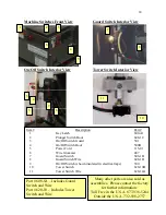
Page 14: ...Guard Information Plate 551 B 6 Meat Stop c w Washer 555 7 Pressure Plate Block Hardware 548 C 8 Pressure Plate Block 547 9 Mold Plate Guard Post 2 551 10 Mold Plate Guard Knob and Washer 2 Required...

Page 15: ...6 Knock Out Arm Bolt 2 502 1 17 Knock Out Shaft Bushing white bushing that is pressed into Machine Frame 462 18 Paper Interleaver Arm Bushing white poly bushing 505 1B Item Description Part 19 Feed Tr...

Page 16: ...Paper Pin Nuts and Washers 525 12 Paper Pin Assembly 524 A 13 Motor Extension Shaft and Screws 517 14 Paper Sleeve Stop 248A 15 Stainless Steel Paper Pivot Rod 2 247 3 Item Description Part 16 Paper...

Page 17: ...46C 5 Ring Pin Pressure Plate 546 3 6 Back Drive Stop Bolt Nut 566 7 Back Drive Stop Bolt 565 8 Mold Plate Back Drive 564 9 Air Grooves colored for visual N A 10 Round Mold Plate 563 1 11 Set of Back...

Page 18: ...oot 500B 5 Power Cord 115 01 6 Wire Grommet 487 7 Guard Switch 608 1B 8 Guard Switch Wire 608 1D 9 On Off Switch shown insulated in electrical tape 500 10 Tower Switch 620 10B 11 Tower Switch Wire 620...

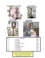
Page 19: ...6 2 Tower Stem 620 3 3 Tower Tube 620 5 4 Tower Block 620 6 5 Tower Locator Lock Bolt 620 7 6 Tower Switch 620 10B 7 Rubber Seal 464S 8 Tower Block Hardware 620 8 9 Tower Jam Nut 620 06 10 Tower Sprin...

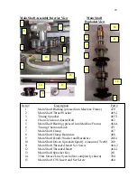
Page 20: ...er Bolt 463 5 Main Shaft Bearing pressed into Machine Frame 464A 6 Timing Chain and Link 471 7 Main Shaft Clamp 467 8 Main Shaft Clamp Hardware 468 9 Main Shaft Fender Washer and Hardware 240 1 10 Mai...

Page 21: ...Crank Shaft 456 7 Crank Housing Bearing 2 pressed into Crank Housing 457A Item Description Part 8 Crank Shaft Sprocket 460 9 Timing Chain and Link 471 10 Crank Arm Hardware 453 11 Connecting Arm Thru...

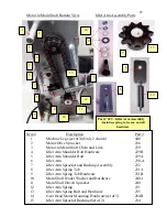
Page 22: ...Idler Arm 230 A 7 Idler Arm Sprocket and Bushing Assembly 232 8 Idler Arm Spring Tab 231A 9 Idler Arm Spring Tab Hardware 231B 10 Main Shaft Fender Washer and Hardware 240 1 11 Main Shaft Driven Spro...

Page 23: ...450 7 Cam Follower Bearing Hardware 475 8 Knock Out Lever Hardware 451 9 Knock Out Lever Bushing Hardware 450B 10 Cam Follower Bearing 474 11 Steel Knock Out Cam Bolts 2 472 S1 12 Steel KO Cam Keeper...

Page 24: ...tside the U S A 732 938 2757 Item Description Part 1 Hopper Bushing Set Collar w screws and o ring 603C 2 Mold Plate Guide Rail 2 Required 494 3 Gear Head Motor 284 4 Motor Spacer 5 Required 2 Shown 2...

Page 25: ...25...

Page 26: ...n that specified or has been tampered with or altered in any way Warranty does not cover parts that wear out from use or parts that are damaged or broken in use or service claims arising due to failur...

Page 27: ...___ Maintenance Performed on Machine______________________________ ___________________________________________________ ___________________________________________________ _____________________________...

Page 28: ..._____________________ ______________________________________________________ ______________________________________________________ ______________________________________________________ _____________...

Reviews: