background image


11 

Touch key 

Extract air mode 

Pressing this key so that it clicks into place activates extract air mode and switches on 

the exhaust air fan. Pressing it again deactivates extract air mode. 

If the ventilation unit is being operated together with a 

fireplace, do not use this touch key unless supply air mode 

is activated at the same time! Simultaneous operation of a 

ventilation system and fireplace imposes more stringent safety 

requirements with regard to low pressure monitoring and a switch-

off function is required for the ventilation unit. 

Touch key 

Supply air mode 

Pressing this key so that it clicks into place activates the supply air mode and switches 

on the supply air fan. Pressing it again deactivates the supply air mode. 

Normal mode 

Pressing both keys so that they click into place switches on both fans.  

Key 

Boost ventilation 

mode/reset filter 

running time 

Function key for boost ventilation mode: 

Pressing this key activates boost ventilation for 15 minutes with an air volume flow 

corresponding to the rotary knob being turned all the way to the right. At the end of the 

15-minute boost ventilation time, the unit reverts to the previous air volume in the 

currently active mode. You can cancel the boost ventilation mode at any time by 

pressing this key again for > 3 s. 


Function key for reset filter running time: 

To ensure cyclic filter inspection, the control has an integrated operating hours counter 

with a fixed running time of 180 d. The boost ventilation mode/reset filter running time 

key allows you to reset the filter running time. To restart the filter running time, press 

and hold this key for > 3 s. 

If the filter running time is reset before the end of 180 d by pressing this key for > 3 s, 

the LED fan symbol will blink rapidly four times in succession to confirm the reset 

operation.  

No reset command can be issued while boost ventilation mode is active!


Table 2: External control panel operating functions 

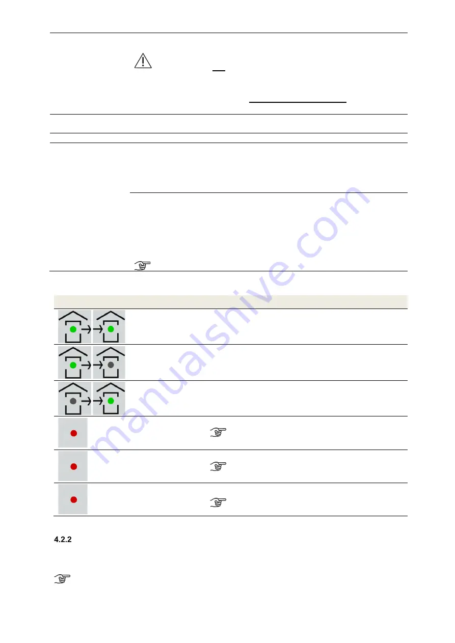
4.2.1.2  Signals used to indicate working/maintenance conditions 

Symbol 

LED signal


Function / Meaning / Action required


Both LEDs light up 

Normal mode (extract air and supply air) 


Extract air symbol 

LED lights up 

Extract air mode is active (extract air only) 


Supply air symbol 

LED lights up 

Supply air mode is active (supply air only) 


Fan symbol 

LED lights up 

Ventilation boost mode is active 

The boost ventilation mode


can be selected while in 

any other mode!


Fan symbol 

LED blinks 

Un-occupied mode is active 

Un-occupied mode


can be selected while in any 

other mode!


Fan symbol 

LED blinks rapidly 

Filter running time has expired; inspect or replace filter 

Boost ventilation mode cannot be activated until a 

reset command is


issued!


Table 3: Functions assigned to LED signals 

  External control signal 0

10 V 

The ventilation unit can be operated with an external 0–10 V control signal. When a 0–10 V analogue signal is 

applied, it is interpreted as a control signal for the fan speed. The current position of the rotary knob on the scale 

marks the point at which the external control voltage becomes effective. 

To make use of the entire external 0–10 V control range, the rotary knob must be pointing to the 

position of the 3rd scaling segment! 

Summary of Contents for FOCUS 200 Base

Page 1: ...Translation of the original instruction manual Heat Recovery Unit FOCUS 200 Base...

Page 2: ...this manual in part or as a whole The information contained in these documents is the property of Zehnder Group Any form of publication whether in whole or in part requires the written approval of Zeh...

Page 3: ...ions 11 External control signal 0 10 V 11 Boost ventilation mode with external boost ventilation key 12 Maintenance by the user 12 Replacing the unit filters 12 Resetting the filter running time 15 Wh...

Page 4: ...chnical description 28 Air connection design versions 28 Technical specification 28 Dimensions 30 FOCUS 200 Base terminal scheme 31 6 Appendices 32 Checklist A Maintenance work for users 32 Checklist...

Page 5: ...the various design variants of the FOCUS heat recovery unit Possible accessories are only described to the extent necessary for appropriate operation of the unit Please refer to the respective instruc...

Page 6: ...if the safety feature is triggered In case of open flue fireplaces for solid fuels the ventilation system must be switched off if the safety feature is triggered The ventilation units for controlled v...

Page 7: ...nt Symbol Meaning Important note Caution Risk of affecting the operation of the ventilation system or damaging the unit Caution Risk of personal injury Safety regulations 3 1 2 1 Safety instructions g...

Page 8: ...osing an installation location it is recommended that you avoid areas with a high average level of humidity ambient conditions for indoor climate control system must not continuously exceed 70 RH at 2...

Page 9: ...product and in case of questions for service The type label is located on the same side of the unit as the air connections and must remain permanently attached to the product Frost protection The FOCU...

Page 10: ...operating functions Description Explanation Intensity scale Rotary knob positioning Operating mode Ventilation with constant air volume flow according to the intensity scale Position 1st scaling segm...

Page 11: ...reset filter running time key allows you to reset the filter running time To restart the filter running time press and hold this key for 3 s If the filter running time is reset before the end of 180...

Page 12: ...hs As part of this process please inspect the other filters in the ventilation system and replace them if necessary The filter mats on the extract air valves e g bathroom kitchen WC should be replaced...

Page 13: ...and heat exchanger out of the EPP housing To do this grip the strap at one end and pull while using your other hand to support the unit Fig 5 Pulling out the EPP foam cover of the filters and heat ex...

Page 14: ...rding to the type label filters with filter class ISO ePM1 must be inserted into the filter compartment of the outdoor air connector The outdoor air connector is indicated by the symbol on the air con...

Page 15: ...of at the end of their useful life in accordance with the applicable regulations in your country 5 Chapter for qualified persons Installation requirements The following requirements must be assured f...

Page 16: ...heck that the wall construction has the necessary load bearing capacity net weight of the FOCUS unit is 25 kg and that the fastening sheet can be mounted securely In case of unsuitable walls we recomm...

Page 17: ...S unit onto the fastening sheet by inserting the lugs B into the slots E in the lock seam at the top of the rear cover Fig 12 Hooking the unit into the fastening sheet Fitting on Floor stand optional...

Page 18: ...ow place the short base part at right angles to the long base part at a staggered height Fig 14 Assembling the base parts 2 Working in the direction of the arrow push the lugs A of the short base part...

Page 19: ...mb vertical and stable Then fix it in this height position with the lock nuts of the adjustable feet Fig 18 Aligning the floor stand 6 Place the FOCUS unit on the floor stand so that the lugs of the f...

Page 20: ...haust air fan when it thaws causing damage to the blades Fig 20 Drainage arrangement for outdoor and exhaust air tubes If an attenuator is fitted at the exhaust air connector it must be routed upwards...

Page 21: ...when The unit is commissioned The siphon starts making slurping gurgling noises We generally recommend using a dry siphon No functional restrictions if it dries out no need for a 2nd siphon Electrical...

Page 22: ...necting cable to the flat connector plug As shown in Fig 24 a J Y St Y 2x2x0 6 cable is recommended as the connecting cable between the control panel and the FOCUS unit The maximum permitted cable len...

Page 23: ...nel connecting terminal Wire of boost ventilation key cable X 07 Wire 1 X 08 Wire 2 GND Table 7 Terminal assignment of boost ventilation key connection Connecting external sensors A sensor controlled...

Page 24: ...total outdoor air volume flow This nominal air volume flow must correspond to a rotary knob position according to the illustration of the control unit Fig 25 Diagram 1 fan speeds parametrisation Fig 2...

Page 25: ...ceed two years Use checklist B to document the maintenance work completed Inspection and cleaning of the heat exchanger In doing so proceed as follows 1 Disconnect the FOCUS unit from the mains power...

Page 26: ...g out the EPP foam cover 5 Holding them by the strap pull the filters E out of the filter compartments Fig 30 Pulling out the filters 6 Holding it by the strap F pull the heat exchanger G out of the E...

Page 27: ...heat exchanger to dry fully before reinstalling it Instructions for proper disinfection can be found at www core life 8 Install the heat exchanger Take care when installing the heat exchanger On the...

Page 28: ...limit value Blinks 4x per second Temperature downstream of pre heater 3K below limit value LED 3 Lights up Pre heater heating up Table 10 Overview of how working conditions are displayed Technical des...

Page 29: ...tance of 3 m unit emission according to DIN EN ISO 3743 1 30 dB A at 155 m h 100 Pa 24 dB A at 200 m h 100 Pa Table 13 Operation data p characteristic curve Note The numerical values shown in the p ch...

Page 30: ...30 Dimensions Fig 33 Dimensional drawing...

Page 31: ...31 FOCUS 200 Base terminal scheme Fig 34 Terminal assignment terminal plan...

Page 32: ...cycle 90 days Quarter Year I II III IV 20 20 20 20 20 20 20 20 20 20 2nd Extract air supplementary filter clean the filters in extract air valves filter replacement cycle approx 2 months Quarter Year...

Page 33: ...ns and clamping assemblies secure yes no Are the regulating and control units functional yes no 3 Ventilation tube heat insulation Has cleaning if necessary been carried out Testing OK For cleaning wh...

Page 34: ...n as planned Cleaning option provided yes no yes no yes no 5 Extract air duct Cleaning option provided yes no 6 Extractor fan Cleaning option provided yes no 7 Control regulation system Operational ye...

Page 35: ...days used very dirty Supply air Fan speed No Room name Project data Measurement data m h m s m h m s Extract air Fan speed No Room name Project data Measurement data m h m s m h m s Pel W The listed...

Page 36: ...36 PDE Manual_Focus 200 Base_V1 1 V1122 DE Subject to change...

Reviews: