9
Control panel
The external control panel allows you to operate the system from a central location. The control panel is only
suitable for use in indoor areas.
Main components
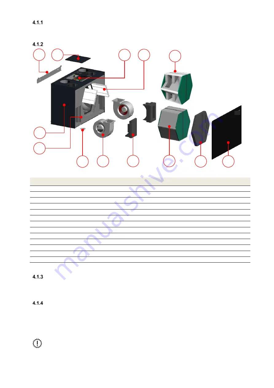
Fig. 1: Main components of the FOCUS ventilation unit
Item
Description
A
Fastening sheet
B
Control cover plate
C
Control board
D
Filter (2x ISO coarse)
E
Summer box (optional)– Module that keeps the air flows thermally separate
F
Housing made from coated sheet steel
G
EPP moulded parts
H
Condensate drain screw connection
I
Fans (2x)
J
EPP foam cover for fan (2x)
K
Heat exchanger with strap and condensate tray
L
EPP foam cover with strap for filter and heat exchanger
M
Front panel made from coated sheet steel
Table 1: FOCUS main components
Type label
The type label identifies the product unequivocally. You will need the details on the type label for the safe use of the
product and in case of questions for service. The type label is located on the same side of the unit as the air
connections and must remain permanently attached to the product.
Frost protection
The FOCUS unit is equipped with automatic frost protection, which prevents the heat exchanger from freezing should
the outdoor air temperature drop to a very low level. The temperature limit for the outdoor air on the unit side is -3 °C.
If the temperature drops below this limit value, the fans are switched off temporarily, unless effective external frost
protection is in place in the system. If an external electric pre-heater (optional) is installed, it is activated by the unit
control system if the temperature drops below the limit value of 0 °C. The only electric pre-heater that may be used
for this purpose is the Iso defroster heater DN125 (Zehnder art. no 527003450).
If an optional hydraulic heating register is installed downstream, please note that the supply air
temperature is not monitored to protect it against freezing!
F
I
J
K
M
H
G
L
C
B
A
D
E
Summary of Contents for FOCUS 200 Base
Page 1: ...Translation of the original instruction manual Heat Recovery Unit FOCUS 200 Base...
Page 30: ...30 Dimensions Fig 33 Dimensional drawing...
Page 31: ...31 FOCUS 200 Base terminal scheme Fig 34 Terminal assignment terminal plan...
Page 36: ...36 PDE Manual_Focus 200 Base_V1 1 V1122 DE Subject to change...


