11
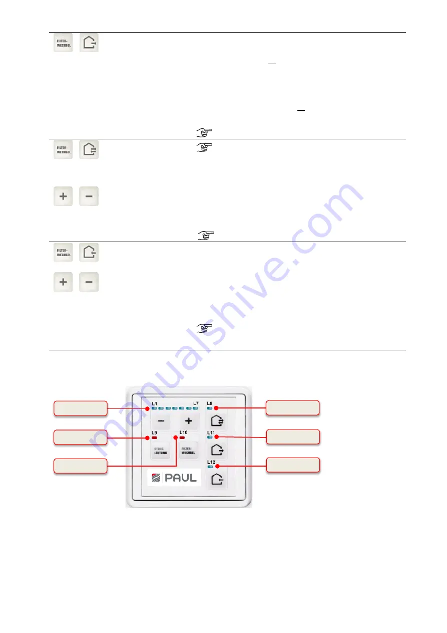
LED L8
LED L11
LED L10
LED L12
LED L9
LED L1 … L7
…
Key combination
configuration mode for
operation together with a
fireplace
Pushing the key combination for at least 3 seconds deactivates the
extract air mode permanently. This status is signalled by LEDs
L8+L11+L12, where L8 and L12 are lit up, L11 blinks 2 times and
then remains switched off. This signal is only visible when holding
the key combination. Activating the extract air mode key in the
deactivated state results in a short 3 time blinking of LED L11 to
signal the deactivated state. Pushing the key combination again for
at least 3 s cancels the key lock. This change is again signalled by
the LEDs L8+L11+L12, where L8 and L12 are lit up, L11 blinks 2
times and then remains switched on. This signal is only visible when
holding the key combination. This enables the extract air mode
again.
Always press the reset filter replacement key first!
…
…
Key combination for the
summer ventilation
temperature limit
configuration mode
Setting keys
The summer ventilation can only be implemented with
an LED control panel if it has been released in the
factory setting.
Pushing the key combination for at least 3 seconds activates the
setting for the temperature limit. This status is signalled by the
blinking of LEDs L8 and L10. With the setting keys the upper
temperature limit for summer ventilation depending on the extract air
temperature can be set between 21 °C (LED L1 lights up) and 27 °C
(LED L7 lights up). After pressing the key combination again for at
least 3 s the setting is saved and the summer ventilation
temperature limit is terminated.
Always press the reset filter replacement key first!
…
…
Key combination
imbalance configuration
mode
Keys
for setting the balance
By pushing the key combination for at least 3s, the imbalance
configuration mode is activated and the LEDs L10 and L12 blink.
The keys for setting the balance can now be used to set the balance
of the fan speeds active upon activation of the imbalance
configuration mode in 5% increments. The balance is not set for
each fan speed individually, but jointly for a group of fan speeds.
The adjustable range is between -
15% (L1) and +15% (L7). In the
central position (L4) the supply air and extract air run with the same
rotational speed. After pressing the key combination again, the
setting is saved and the imbalance configuration mode concluded.
Always press the reset filter replacement key first!
1st
group
fan speeds <1+2>
2nd group
fan speeds < 3 +4+5>
3rd group
fan speeds <6+7>
Table 2: Control functions of the LED control panels
4.2.1.2 Signals used to indicate operating and error conditions
Fig. 3: LED signals LED control panel
Summary of Contents for FOCUS 200 Base
Page 1: ...Translation of the original instruction manual Heat Recovery Unit FOCUS F 200...
Page 49: ...49 Dimensions Fig 43 Dimensional drawing FOCUS...
Page 50: ...50 FOCUS circuit plan Fig 44 Terminal assignment circuit diagram FOCUS...
Page 51: ...51 Master Controller terminal assignment Fig 45 Master Controller terminal assignment...


