14
Signal
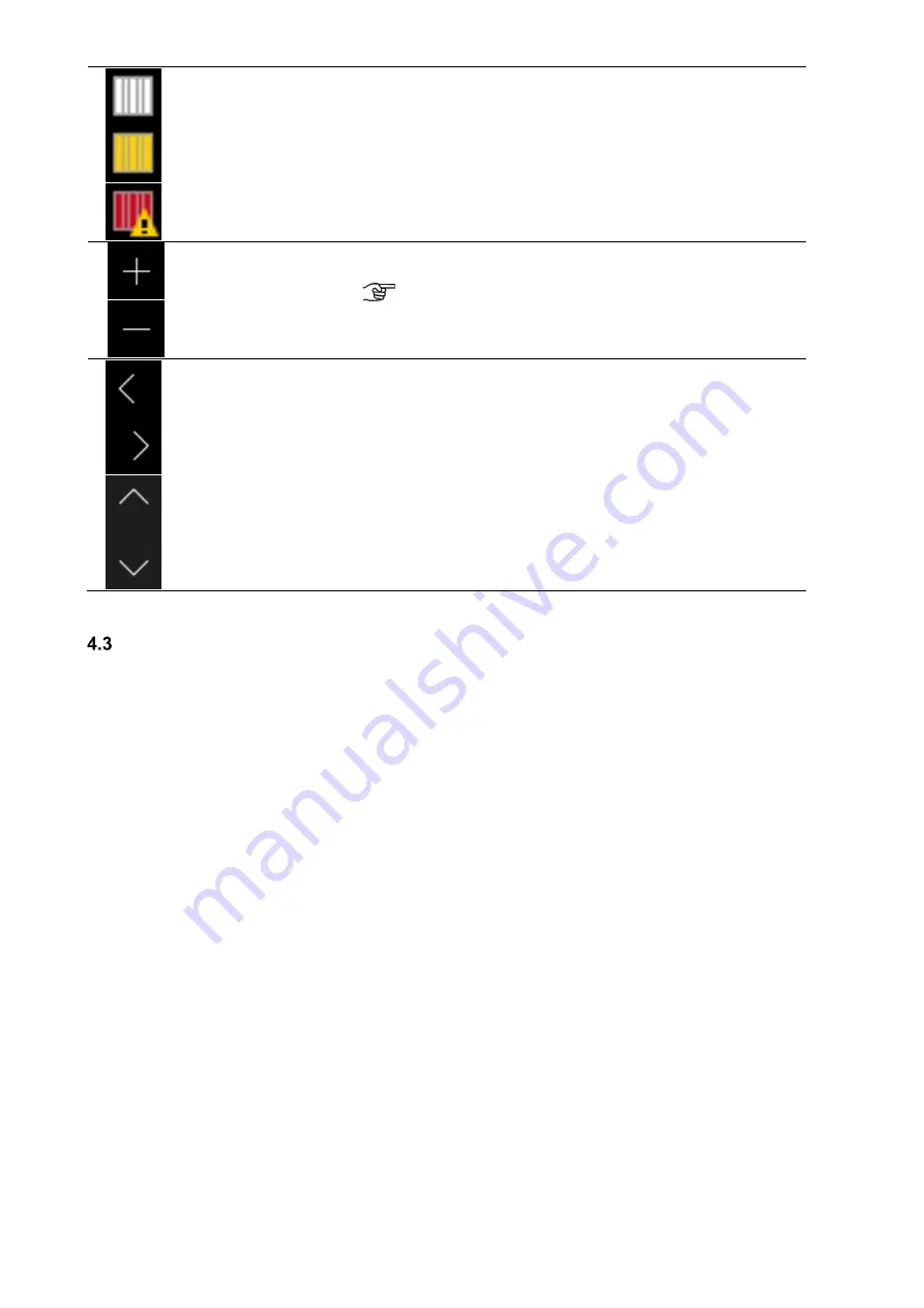
Filter symbol/filter
running time
To ensure cyclic filter inspection, the control has an integrated
operating hours counter. The operating time is subtracted in a count-
down manner from the pre-set filter running time and indicated in days
under the filter symbol.
The filter symbol colour changes from white to yellow, when the filter
running time ≤ 10 d and from yellow to red if the filter running time has
expired.
When the filter runtime is expired the message “replace filter” is
created.
Buttons
+ /
-
By touching the button, you can change the menu values (e.g. fan
speeds in 1% increments or the time in minute or hour increments).
The data is only saved when the enter button is touched!
Buttons
Navigation
By touching the navigation buttons left/right and up/down you can
navigate in the menus to select the desired parameter in the
respective menu level. If several values can be adjusted in a menu
(e.g. for date and time: day, month, year, hours, minutes) you can
select the individual values to be adjusted and then change them via
+/
-.
Table 4: TFT control panel operations and signals
Menu structure of the TFT control panel
The menu structure consists of the start menu and the three main menus (Information, Settings and Setup). The start
menu is shown upon activation of the TFT touch pad. The main menus are each divided into sub-menus that allow
access to information or parameter changes.
Summary of Contents for FOCUS 200 Base
Page 1: ...Translation of the original instruction manual Heat Recovery Unit FOCUS F 200...
Page 49: ...49 Dimensions Fig 43 Dimensional drawing FOCUS...
Page 50: ...50 FOCUS circuit plan Fig 44 Terminal assignment circuit diagram FOCUS...
Page 51: ...51 Master Controller terminal assignment Fig 45 Master Controller terminal assignment...


