16
4.3.1.3 Sub-menu Fan speeds
In this sub-menu the percentage settings of the three fan speeds 1, 2 and 3 (FS1, FS2, and FS3) as well as the pre-
set active times for the un-occupied mode and boost ventilation mode are shown.
4.3.1.4 Sub-menu Current device status
In this sub-menu, the current unit-side supply air temperature and outdoor air temperature as well as the bypass
status (closed/open) for units with bypass shutter or the summer ventilation status (active/inactive) for units without
bypass shutter, are shown.
4.3.1.5 Sub-menu Software versions
In this sub-menu, the unit type along with the hardware and software status of the controllers included in the control
system are shown.
4.3.1.6 Sub-menu Connected units
In this sub-menu check marks indicate which units are actually connected to the internal unit BUS and recognised by
it.
4.3.1.7 Sub-menu Filter running time
In this sub-menu the pre-set filter running time and the current remaining filter running time are shown. The remaining
filter-running time is counted down every calendar day of operation of the ventilation unit. In addition, when the pre-
set filter running time is exceeded by more than 0 days, the message “Filter running time exceeded by xxx day”, is
shown.
4.3.1.8 Sub-menu Operating hours
The sub-menu shows:
•
Total operating hours (time during which the unit is connected to the mains voltage)
•
Fan operating hours (time in which the fans are operating)
Main menu Settings
In the main menu
Settings
users can make changes that primarily serve the individual adjustments that primarily
serve adjustment to their individual comfort. The respective sub-menus are selected with the navigation buttons and
opened via Enter. Only sub-menus with text shaded in red can be parametrised.
The settings in the sub-menus are only saved when the enter button is touched!
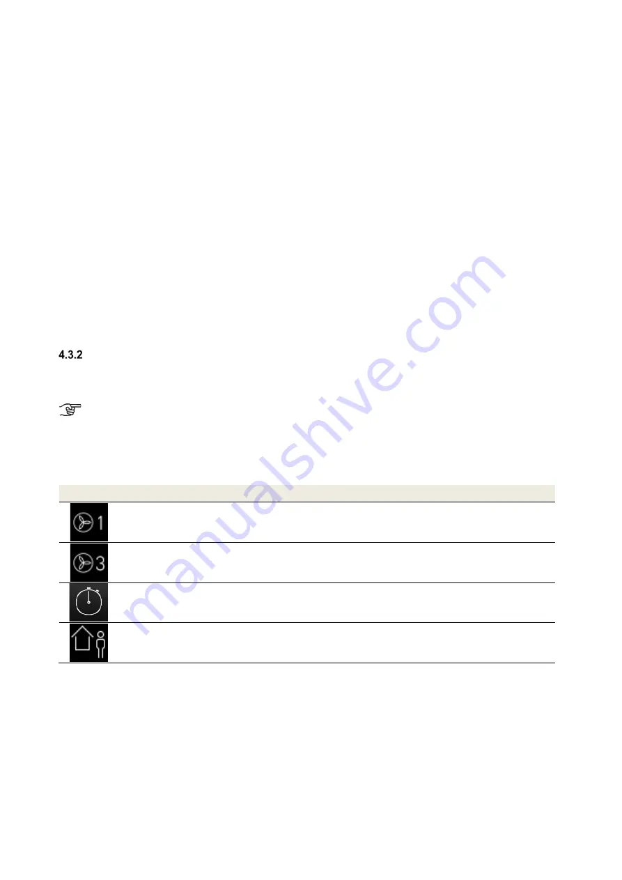
4.3.2.1 Sub-menu Fan speeds
The following can be selected and adjusted with the navigation buttons:
•
Fan speed 1 and fan speed 3 (in 1% increments)
•
Duration of the boost ventilation (in 5 -minute increments)
•
Fan intensity for un-occupied times (FS1 in min/h increments)
Symbol Description
Explanation/Actions
Button
Fan speed 1 (FS1)
Activate FS1 with the button fan speed 1 and parametrise it with the
navigation buttons.
Setting range: 17% < FS1 < FS2
Button
Fan speed 3 (FS3)
Activate FS3 with the navigation button fan speed 3 and parametrise
it with the navigation buttons.
Setting range: FS2 < FS3 < 100%
Permanent boost ventilation
Settings: 15 min …120 min,
the air volume flow of the boost ventilation is equal to fan speed 3.
Fan intensity for the duration
of the un-occupied time for
moisture protection
Settings: 15 min/h, 30 min/h, 45 min/h,
the ventilation intensity of the active time of the interval is equivalent
to fan speed 1.
Table 5: Parametrisation sub-menu fan speeds
Summary of Contents for FOCUS 200 Base
Page 1: ...Translation of the original instruction manual Heat Recovery Unit FOCUS F 200...
Page 49: ...49 Dimensions Fig 43 Dimensional drawing FOCUS...
Page 50: ...50 FOCUS circuit plan Fig 44 Terminal assignment circuit diagram FOCUS...
Page 51: ...51 Master Controller terminal assignment Fig 45 Master Controller terminal assignment...


