23
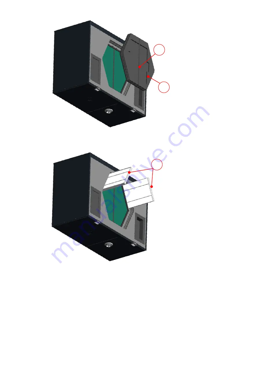
Fig. 11: Pulling out the EPP foam cover of the filters and heat exchanger
5. Holding them by the strap, pull the filters
E
out of the filter compartments.
Fig. 12: Pulling out the filters
6. On the filter frame of each filter, there is an arrow to indicate the prescribed direction of flow. Insert the new
filters according to their designated direction of flow
F
.
D
C
E
Summary of Contents for FOCUS 200 Base
Page 1: ...Translation of the original instruction manual Heat Recovery Unit FOCUS F 200...
Page 49: ...49 Dimensions Fig 43 Dimensional drawing FOCUS...
Page 50: ...50 FOCUS circuit plan Fig 44 Terminal assignment circuit diagram FOCUS...
Page 51: ...51 Master Controller terminal assignment Fig 45 Master Controller terminal assignment...


