28
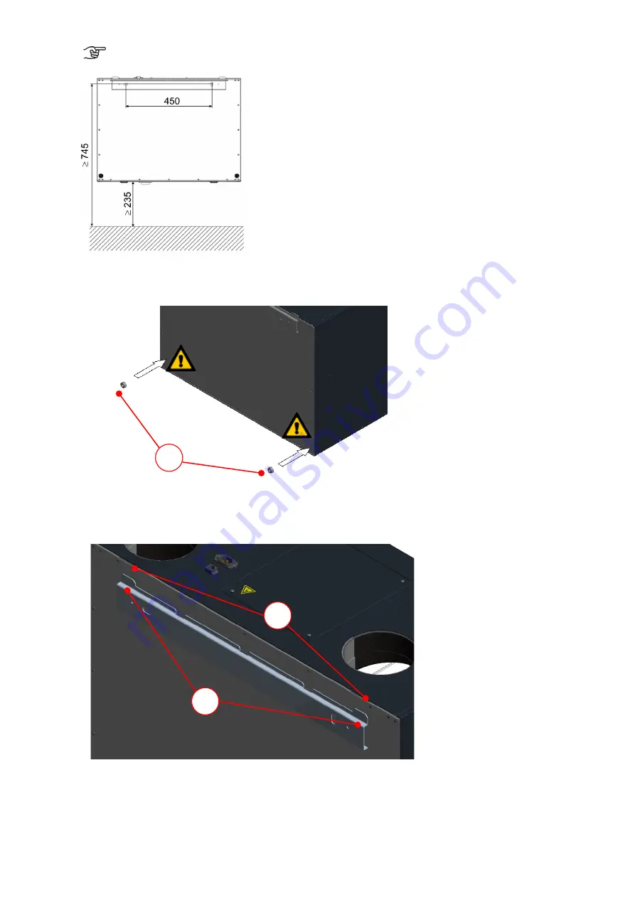
Observe the minimum distance required in relation to the finished floor!
Fig. 17: Wall mounting (version LEFT)
2. Stick one of the supplied self-adhesive spacers
D
in each corner on the rear of the unit.
Fig. 18: Spacers mounting
3. Hook the FOCUS unit onto the fastening sheet by inserting the lugs
B
into the slots
E
in the lock seam at the
top of the rear cover.
Fig. 19: Hooking the unit into the fastening sheet
D
E
B
Summary of Contents for FOCUS 200 Base
Page 1: ...Translation of the original instruction manual Heat Recovery Unit FOCUS F 200...
Page 49: ...49 Dimensions Fig 43 Dimensional drawing FOCUS...
Page 50: ...50 FOCUS circuit plan Fig 44 Terminal assignment circuit diagram FOCUS...
Page 51: ...51 Master Controller terminal assignment Fig 45 Master Controller terminal assignment...


