29
Fitting on Floor stand (optional)
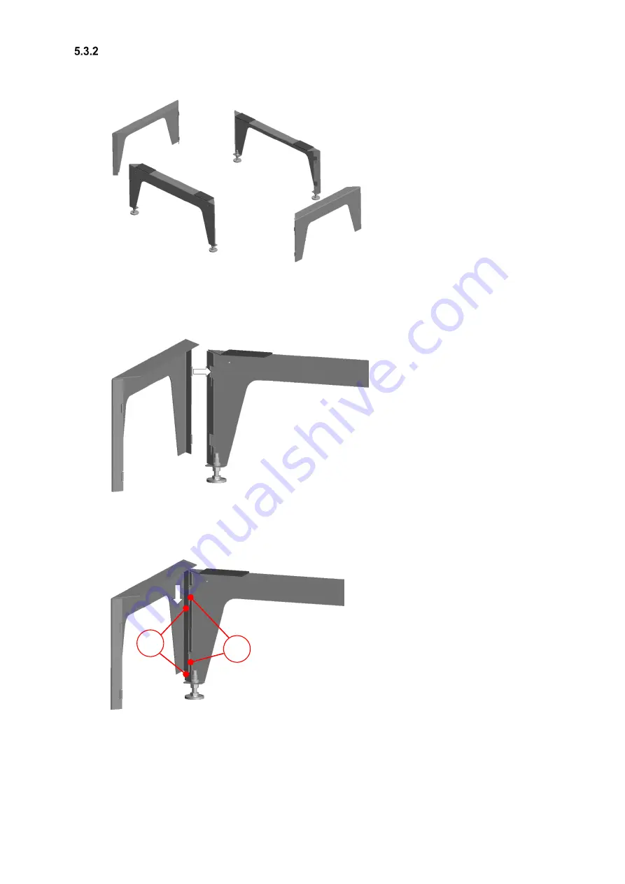
The dimensions of the floor stand are as follows: footprint = (630 x 300) mm; variable height adjustment = between
280 mm and 320 mm using adjustable feet. The floor stand consists of two long base parts (each with two adjustable
feet) and two short base parts.
Fig. 20: Individual parts of the floor stand
Assemble the individual parts of the floor stand as shown in the illustrations. Proceed as follows.
1. Working in the direction of the arrow, place the short base part at right angles to the long base part at a
staggered height.
Fig. 21: Assembling the base parts
2. Working in the direction of the arrow, push the lugs
A
of the short base part into the guide slots
B
of the long
base part so that they engage and fix the two base parts together.
Fig. 22: Fixing the two base parts
3. Now connect the other two base parts in the same way.
A
B
Summary of Contents for FOCUS 200 Base
Page 1: ...Translation of the original instruction manual Heat Recovery Unit FOCUS F 200...
Page 49: ...49 Dimensions Fig 43 Dimensional drawing FOCUS...
Page 50: ...50 FOCUS circuit plan Fig 44 Terminal assignment circuit diagram FOCUS...
Page 51: ...51 Master Controller terminal assignment Fig 45 Master Controller terminal assignment...


