33
Electrical connections
Electrical connections are to be implemented in accordance with the standards
specific to the relevant country and by qualified personnel only!
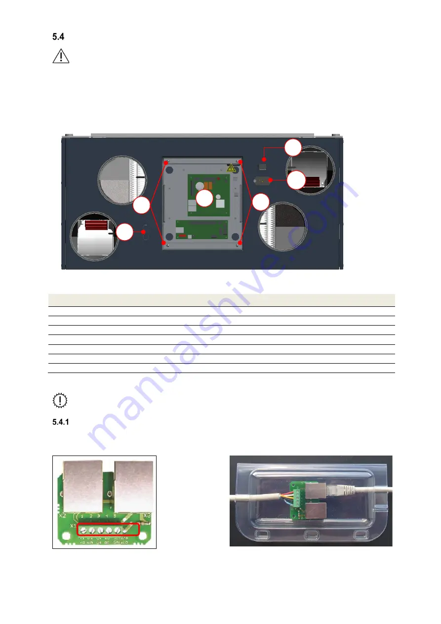
The electrical mains power supply of the FOCUS is via the 3-core non-heating device plug connection
A
with the
mains cable. The CAT5 network cable is connected to the RJ45 socket
B
. Both plug connections are found on the
top of the unit next to the cover sheet of the control. The cover sheet is fixed flush with the surface with 4 screws
C
.
Analogue and digital input/output signals from sensors (e.g. room air quality sensors) or actuators (e.g. boost
ventilation keys) are connected to the corresponding clamping points of the Master controller
D
under the cover plate.
As needed, the cable guides that are pre-punched in the casing sheet
E
must be broken out and the cables of the
sensors/actuators guided through the cable glands M16.
Fig. 30: Side of the casing with electrical connections
Item
Description
A
3-- pole rubber connector
B
RJ45 socket
C
Cover plate screws (4x)
D
Master Controller
E
Pre-punched cable guide (3x) for M16 cable gland
FOCUS circuit plan
Master Controller terminal assignment
Table 19: Overview of the electrical connections
The RJ45 plug connection only serve the internal system RS485-BUS! Any other use results
in damage to the control and operating modules!
Adapter board connection
The adapter board with the double RJ45 plug connection and the 5-core screw terminal X1 serve the communication
of the modules via the internal RS485-BUS. The CAT5 network cable creates the internal connection between the
RJ45 socket of the NOVUS and one of the two RJ45 sockets of the adapter board.
Fig. 31: Adapter circuit board
Fig. 32: Housing for adapter board
A shielded 4-core cable is connected to the 5-pin screw terminal of the adapter board, which connects the adapter
board with the 5-pin screw terminal of the connection board of the control panel. To protect it from faulty voltage,
short circuits and dust, the adapter board must be mounted in the clear plastic housing. The cables connected to the
A
B
E
C
C
D
X1
Summary of Contents for FOCUS 200 Base
Page 1: ...Translation of the original instruction manual Heat Recovery Unit FOCUS F 200...
Page 49: ...49 Dimensions Fig 43 Dimensional drawing FOCUS...
Page 50: ...50 FOCUS circuit plan Fig 44 Terminal assignment circuit diagram FOCUS...
Page 51: ...51 Master Controller terminal assignment Fig 45 Master Controller terminal assignment...


